
Your dashboard, your way. Create your own Custom Monitoring Dashboards tailored to your needs.
What is a Monitoring Dashboard?
A Domotz Monitoring Dashboard is a customizable dashboard that you can create to monitor information about the devices you choose, from different Domotz Agents (Sites).
In addition, on Domotz Monitoring Dashboards, you can configure, display, and set alerts on any type of sensor (SNMP, OS monitoring, Automation & Drivers, etc.) values on multiple devices, across different sites.
You can create and edit multiple Monitoring Dashboards and include different widgets (limited to Monitoring Tables at the moment) in each Dashboard. All Monitoring Dashboard are shared across the entire account so that each Team Member can see the Monitoring Dashboards created by a colleague. Access to the devices may be limited based on a Team Member’s permissions.
How to create a Monitoring Dashboard
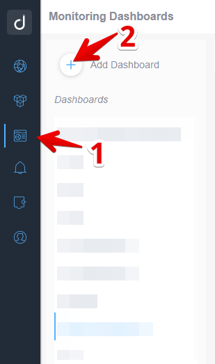
Select the “Monitoring Dashboards” section from the Domotz main menu, and then click on “Add Dashboard”:
Accessing and Creating a Monitoring Dashboard
1. In the navigation menu on the left, select the second icon from the top, resembling a dashboard, to access the Monitoring Dashboards section.
2. In the top right of the main section, click on "Add Dashboard" to create a new dashboard.
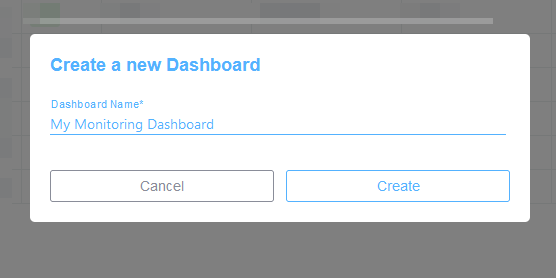
Insert a unique Monitoring Dashboard name:
Creating a New Dashboard
1. Enter a name for the dashboard in the "Dashboard Name" field, e.g., "My Monitoring Dashboard".
2. To proceed, click the "Create" button.
3. To cancel the operation, click the "Cancel" button.
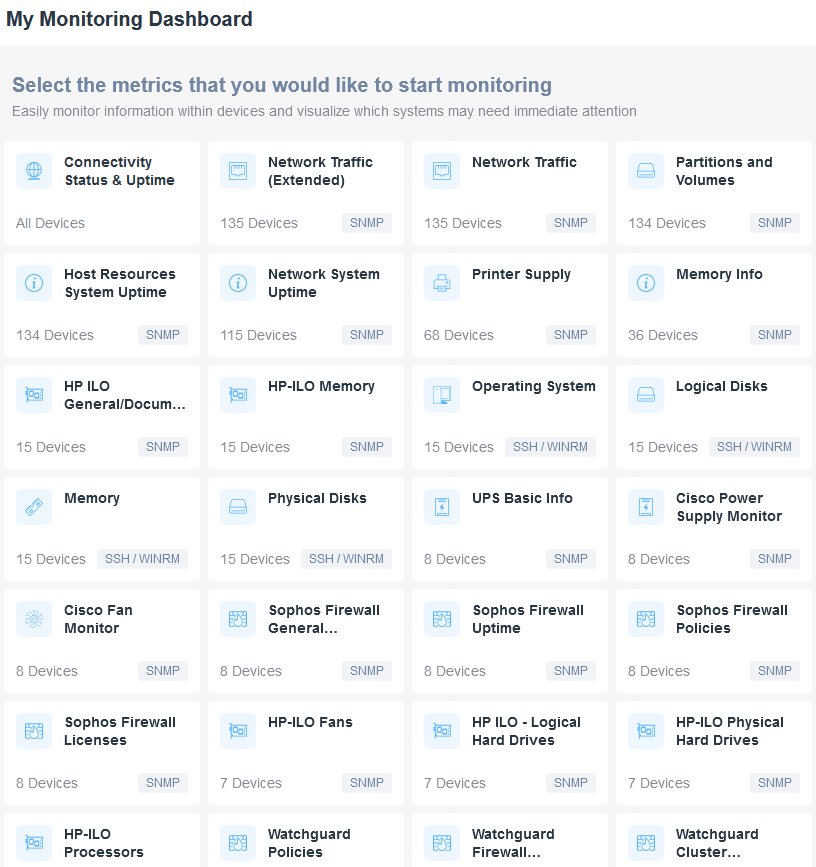
and start adding your Monitoring Tables to the newly created Dashboard, by choosing a Domotz Monitoring Table templates:
Monitoring Dashboard Selection Guide
1. The dashboard displays a list of metrics for monitoring device information and system statuses.
2. Choose metrics such as "Connectivity Status & Uptime" or "Network Traffic" to monitor specific aspects. Each option shows the number of devices and the protocol used, like SNMP or SSH/WINRM.
3. For device-specific monitoring, options like "Host Resources System Uptime" or "Printer Supply" provide detailed insights.
4. To track hardware elements, select "Memory," "Physical Disks," or "UPS Basic Info."
5. For firewall or network devices, use options like "Cisco Power Supply Monitor," "Sophos Firewall General," or "Watchguard Policies."
6. Each metric presents useful device count and protocol information for tailored monitoring needs.
Monitoring Dashboard Metric Selection
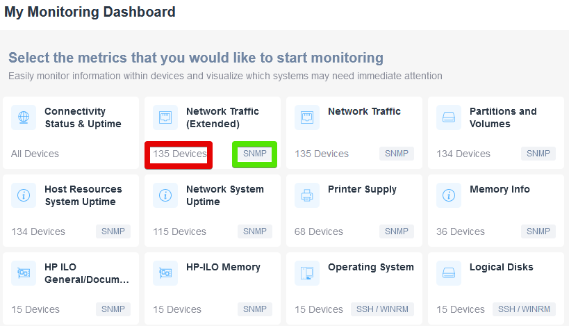
1. Title: "My Monitoring Dashboard" indicates the page for selecting metrics to monitor devices.
2. Instruction: "Select the metrics that you would like to start monitoring" provides guidance on choosing metrics.
3. Categories include options like Connectivity Status & Uptime, Network Traffic (Extended), Network Traffic, and others.
4. Each category displays the number of devices being monitored, such as 135 Devices for "Network Traffic (Extended)" and 134 Devices for "Partitions and Volumes."
5. "Network Traffic (Extended)" is highlighted with 135 Devices and the protocol "SNMP" emphasized, suggesting significance.
6. Additional metrics include options for monitoring Host Resources System Uptime, HP ILO General/Documentation, and more, each showing device counts and protocols like SNMP or SSH/WINRM.
Creating and Editing Monitoring Tables
Once selected a Monitoring Table template, you will be able to customize both the default device columns (Device Information) and the template specific ones (in this case the Connectivity Status & Uptime templates):
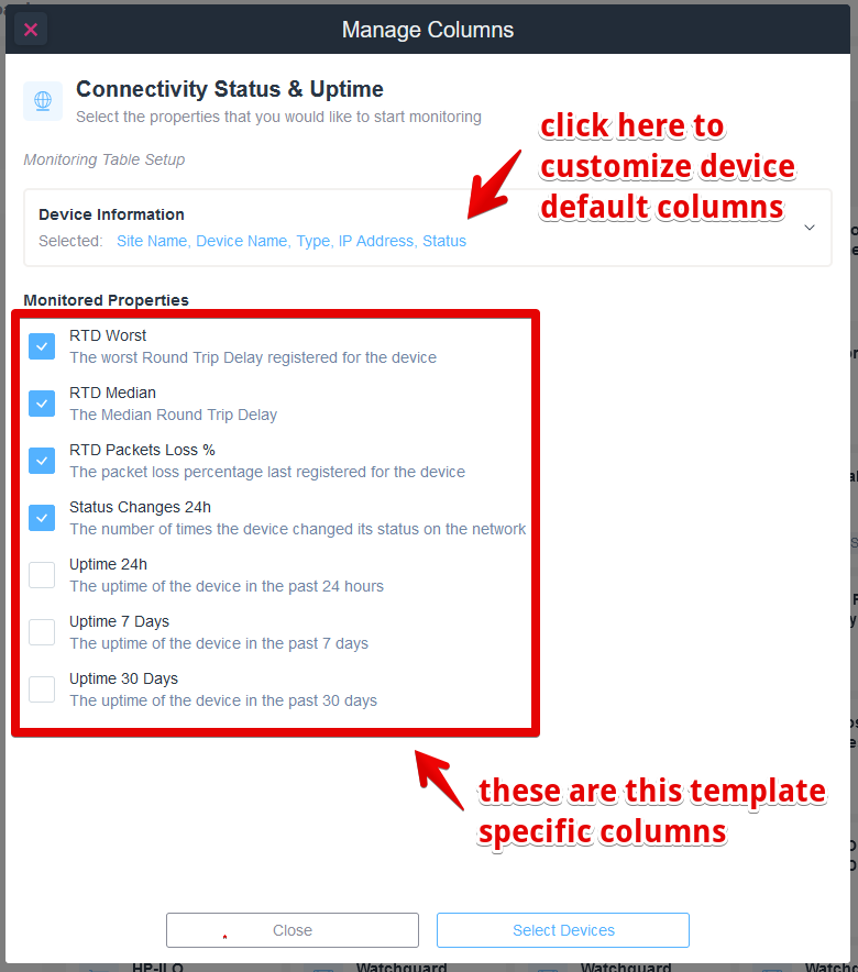
Manage Columns Dialog for Connectivity Status and Uptime
1. To customize device default columns, click the link next to "Device Information." Selected columns include Site Name, Device Name, Type, IP Address, and Status.
2. In the "Monitored Properties" section, select or deselect checkboxes for specific monitoring data:
- RTD Worst: Tracks the worst Round Trip Delay registered for the device.
- RTD Median: Shows the Median Round Trip Delay.
- RTD Packets Loss %: Displays the last registered packet loss percentage for the device.
- Status Changes 24h: Counts the number of times the device changed status on the network.
3. Optional additional columns for uptime include:
- Uptime 24h: Uptime in the past 24 hours.
- Uptime 7 Days: Uptime in the past 7 days.
- Uptime 30 Days: Uptime in the past 30 days.
4. Use "Select Devices" to apply changes or "Close" to exit without saving.
Device Information Columns
If clicked, you will be able to add/remove the device information columns:
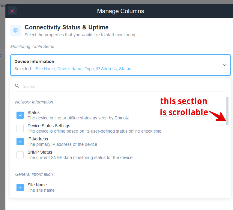
Manage Columns for Connectivity Status & Uptime
1. Select the properties you want to monitor under "Connectivity Status & Uptime."
2. In the "Device Information" section, options like Site Name, Device Name, Type, IP Address, and Status are available. Click to select or deselect.
3. The "Network Information" section allows toggling options such as Status, Device Status Settings, IP Address, and SNMP Status.
4. The "General Information" section includes Site Name.
5. Use the scroll bar on the right to access more options.
Template Specific Columns
Here instead you will be able to add/remove the selected template specific columns.
Following an example from the “Connectivity Status & Uptime” template:
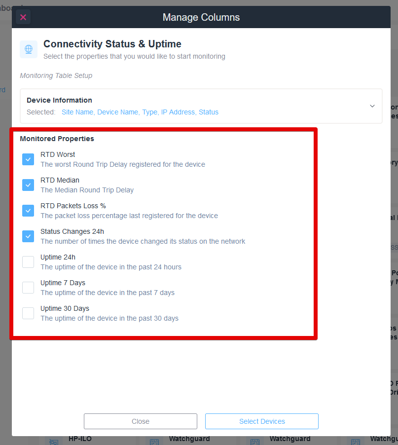
Configure Monitored Properties in Connectivity Status & Uptime.
1. Open the "Manage Columns" window.
2. Under "Connectivity Status & Uptime," select the properties to monitor.
3. In the "Monitored Properties" section, check the boxes for:
- "RTD Worst" for the worst round trip delay.
- "RTD Median" for the median round trip delay.
- "RTD Packets Loss %" for the packet loss percentage.
- "Status Changes 24h" for status changes within 24 hours.
4. Optionally, check the boxes for "Uptime 24h," "Uptime 7 Days," and "Uptime 30 Days" to monitor device uptime over different periods.
5. Click "Select Devices" to apply the changes or "Close" to exit without saving.
This is instead from the ‘Network Traffic’ template:
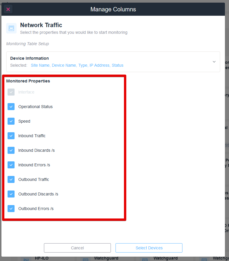
Managing Network Traffic Monitoring Columns
1. In the "Manage Columns" window under "Network Traffic," select properties to monitor.
2. Under "Device Information," view selected attributes such as Site Name, Device Name, Type, IP Address, and Status.
3. In "Monitored Properties," check the options: Operational Status, Speed, Inbound Traffic, Inbound Discards/s, Inbound Errors/s, Outbound Traffic, Outbound Discards/s, and Outbound Errors/s.
4. Click "Select Devices" to apply changes or "Cancel" to exit without saving.
Device Selection
After selecting the information which will be displayed in the Monitoring Table template, you will be able to add the devices you would like to include in the selected Monitoring Table template:
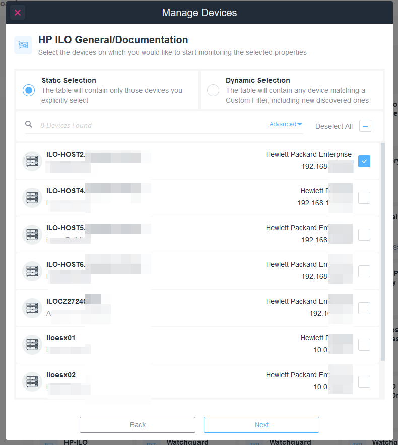
Manage Devices Interface for Selecting Devices to Monitor
1. Navigate to the "Manage Devices" section to begin monitoring device properties.
2. Choose between "Static Selection" and "Dynamic Selection." "Static Selection" allows you to manually select devices. "Dynamic Selection" automatically includes devices matching a custom filter.
3. Below the selection options, a list of devices is displayed. Each device entry includes the device name, IP address, and associated organization, such as "Hewlett Packard Enterprise."
4. Check the box next to a device to select it for monitoring. Ensure at least one device is selected if "Static Selection" is chosen.
5. Use the "Advanced" link for additional filter options if needed.
6. Click "Deselect All" if you want to clear all current selections.
7. Once selections are made, click the "Next" button at the bottom to proceed. Use "Back" to return to the previous step.
Static and Dynamic Tables
You can create a Static or Dynamic table:
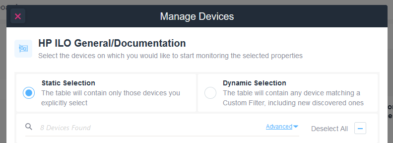
Manage Devices Selection Options
1. Choose a selection type:
- Static Selection: Select this to include only devices you manually choose.
- Dynamic Selection: Select this to include any device that matches a Custom Filter, and automatically add newly discovered devices.
2. Below the selection options, there's a search bar with the placeholder text "8 Devices Found."
3. Advanced settings and a "Deselect All" option are available to refine or clear your selection.
Static tables will contain only those devices which you will select at the time that you create the table.
Dynamic tables instead, will automatically add a new device to the table once it will find a device which matches the selected template.
For example if you have created a table which is monitoring HP-ILO disks, if a new HP-ILO controller is found on the network by Domotz it will be automatically added to that table.
After selecting the devices you would like to monitor and clicking “Next” you will be able to edit the Table Name and display the monitoring table:
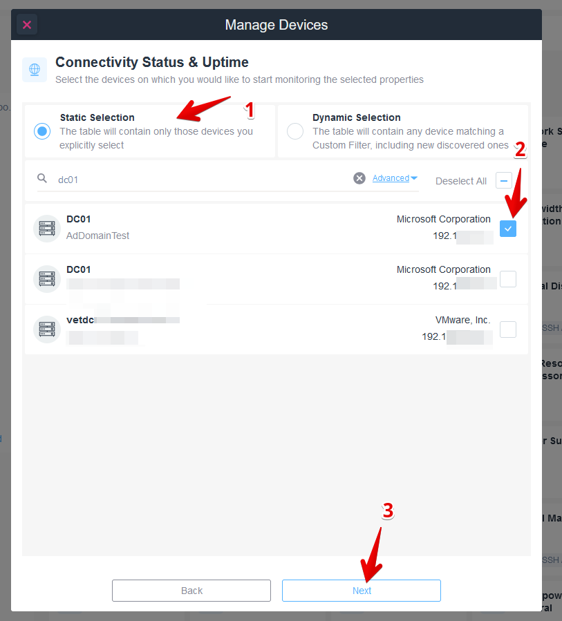
Manage Devices Connectivity Status & Uptime
1. Select "Static Selection" to manually choose devices for monitoring.
2. Check the box next to the Microsoft Corporation device labeled with IP address 192.1 to select it for monitoring.
3. Click the "Next" button to proceed with the selected devices.
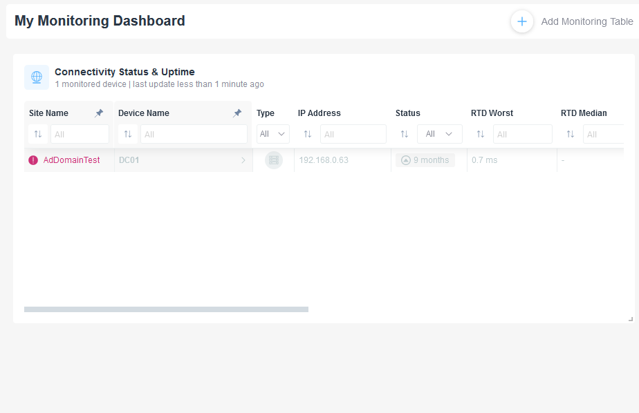
Monitoring Dashboard Overview
1. The dashboard header displays "My Monitoring Dashboard" with an option to "Add Monitoring Table" on the top right.
2. The "Connectivity Status & Uptime" section shows one monitored device with a recent update.
3. Column headers include Site Name, Device Name, Type, IP Address, Status, RTD Worst, and RTD Median. These columns allow filtering options.
4. Listed entry: Device with site name "AdDomainTest" and device name "DC01" has IP address "192.168.0.63" and a status that indicates 9 months of connectivity. RTD Worst value is 0.7 ms, while RTD Median is not available.
Editing an already created Monitoring Table
You will be able to edit a monitoring dashboard by using the ‘Actions’ menu at top right of the monitoring table which will be shown by hovering the chosen table to edit:
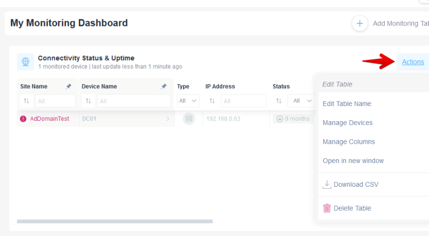
Monitoring Dashboard Actions Menu
1. Navigate to "My Monitoring Dashboard" to view device connectivity status and uptime.
2. In the "Connectivity Status & Uptime" section, review the list showing site name, device name, type, IP address, and status.
3. To perform actions, click on "Actions" at the top right corner of the section.
4. In the dropdown menu, you have options to edit the table name, manage devices, manage columns, open in a new window, download data as a CSV file, or delete the table.
Using this menu you will be able to:
- edit the table name
- add/remove devices from the monitoring dashboard
- add/remove columns
- detach the monitoring table from the dashboard and open it in a new window which can be moved to another monitor
- download a csv containing all the sensor values for the monitored devices in that table
- delete the monitoring table
Each Monitoring Dashboard can contain multiple Monitoring Tables, allowing you to monitor all the relevant devices of multiple Sites/Customers in a single view:
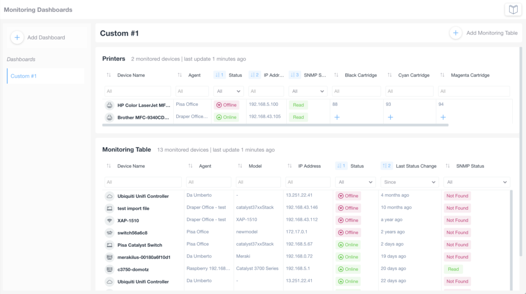
Dashboard Overview for Monitoring Devices
1. The left panel displays a navigation menu with options to "Add Dashboard" and shows a list of dashboards, including "Custom #1."
2. The main section is divided into two tables: "Printers" and "Monitoring Table."
3. The "Printers" table includes columns for Device Name, Agent, Status, IP Address, and Cartridge levels (Black, Cyan, Magenta). Device status is indicated as Online or Offline, with color codes for quick reference.
4. The "Monitoring Table" lists devices with columns for Device Name, Agent, Model, IP Address, Status, Last Status Change, and SNMP Status. Devices are marked as Online or Offline, with details on when the status last changed.
5. Filters are available for refining the display by different criteria such as status change dates or SNMP status.
Monitoring Tables examples
Following you will see some monitoring tables examples

Printer Supply Status Overview
1. The table displays a list of monitored printers, with details on their current supply levels.
2. The "Agent" column shows the location or entity managing each printer.
3. The "Device Name" column lists the printer models, such as Brother MFC-9340CDW and HP Color LaserJet MFP M477.
4. The highlighted section focuses on the "Supply Unit" and "Supply Level" columns.
5. "Supply Unit" details the specific component of each printer, such as Black Drum Unit or Cyan Cartridge.
6. "Supply Level" indicates the percentage of supply remaining for each unit, with progress bars visualizing the data, for example, Black Drum Unit at 62% and Magenta Cartridge at 47%.
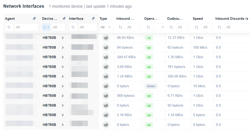
Network Interfaces Overview
1. The table displays a list of network interfaces with columns for Agent, Device, Interface, Type, Inbound and Outbound data, Operational status, Speed, and Inbound Discards per second.
2. Each row represents a different network interface with specific data such as inbound and outbound traffic in KB/s or MB/s, and operational status shown as "up" or "down."
3. The Speed column indicates the maximum speed capacity of each interface, for example, 1 Gb/s or 100 Mb/s.
4. The Inbound Discards column shows any discards occurring per second, with all values in this list noted as 0.0.
5. Filters and sorting options are available for each column to customize the display of information for easier analysis.
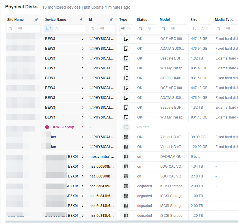
Overview of Physical Disks Status
1. The table displays information about physical disks, including columns for Site Name, Device Name, Id, Type, Status, Model, Size, and Media Type.
2. Each row lists details for a specific device. For example, devices named "BEW3" have a status of "OK" with varying models and sizes.
3. The "BEW3-Laptop" device has a unique identifier display and shows "No data" in the status column.
4. The status column includes entries such as "OK", "on", and "degraded", indicating the current state of each device.
5. Devices under ".ESX01" show mixed statuses of "on" and "degraded", with corresponding type and media details.
6. The list is noted as being updated 1 minute ago, ensuring the information is current.
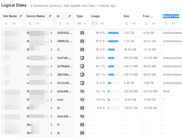
Logical Disk Overview in a Monitoring System
1. The table displays information about monitored logical disks across devices.
2. Columns include Site Name, Device Name, Id, Type, Usage, Size, Free Space, and Mount Point.
3. Site Name filters allow sorting and selection for specific monitoring locations.
4. Device Name and Id provide identification details for each device.
5. Type indicates the disk type, with icons illustrating whether it's physical or virtual.
6. Usage column shows disk usage percentages with visual progress bars for clarity.
7. Size and Free Space columns display the total disk size and available free space.
8. Mount Point column indicates the directory location or volume path for each disk.
Monitoring Table Settings
SNMP Sensors
When an SNMP sensor is selected as one table property (column), not all the devices in that table may have it configured. When the sensor is not configured a “+” icon will appear in the cell, allowing you to add it to the device immediately. Once added, within a few minutes, the value will be fetched and displayed on the table.
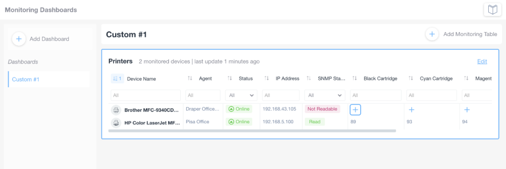
Printer Monitoring Dashboard Overview
1. Navigate to the "Monitoring Dashboards" section.
2. Click on "Custom #1" under the Dashboards menu to view detailed printer information.
3. In the "Printers" section, observe the following data points:
- Device Name: Lists printer models such as "Brother MFC-9340CD" and "HP Color LaserJet MF."
- Agent: Displays the location or office associated with each printer, such as "Draper Office" and "Pisa Office."
- Status: Indicates current status, such as "Online."
- IP Address: Shows the network address for each printer.
- SNMP Status: Describes the connection status, noting "Not Readable" or "Read."
4. View cartridge levels for Black, Cyan, and Magenta with corresponding numeric values.
5. Use the "Add Dashboard" and "Add Monitoring Table" options to customize monitoring views.
Column Options:
All the table columns offer the following options for each of the different columns:
- Filter
- Sort – also available for multiple columns
- Drag to change columns order
- Resize
- Rename
- Pin to side
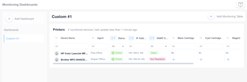
Monitoring Dashboards Interface Overview
1. On the left sidebar, find and click on "Custom #1" under Dashboards to access the specific monitoring dashboard.
2. In the main view, the dashboard is labeled "Custom #1" with a printers section displaying monitored devices.
3. The table lists printers with columns for Device Name, Agent, Status, IP Address, SNMP Status, and various cartridge levels.
4. Devices include "HP Color LaserJet MFP" and "Brother MFC-9340CDW", both showing as "Online" under Status.
5. IP addresses are listed: "192.168.5.100" for the first printer and "192.168.43.105" for the second.
6. SNMP Status indicates "Read" for the first printer and "Not Readable" for the second.
7. Cartridge levels for Black, Cyan, and Magenta are shown with numeric values and add options.
You can select the edit option by moving the mouse over the column header.
Grid view
You can put your monitoring tables in a grid view by resizing them and dragging them to the preferred area of your screen:
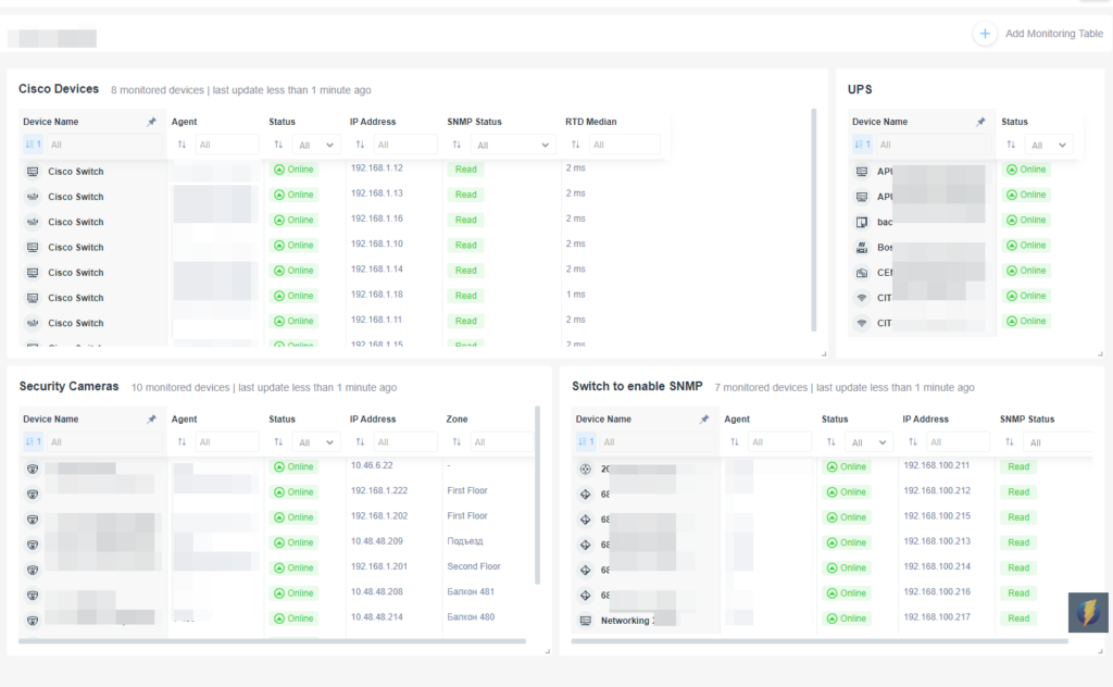
Network Monitoring Dashboard Overview
1. **Cisco Devices Section**: Lists multiple Cisco switches with columns displaying device name, agent, status, IP address, SNMP status, and RTD median. All devices are marked as "Online" with IP addresses starting from 192.168.1.12 to 192.168.1.15. SNMP status shows "Read" for each device.
2. **UPS Section**: Displays devices with their names and statuses. All devices are shown as "Online." Filters at the top allow sorting by device name and status.
3. **Security Cameras Section**: Includes details for various security cameras with columns for device name, agent, status, IP address, and zone location. All cameras are "Online," with varied IP addresses and listed zones such as "First Floor" and "Балкон 481."
4. **Switch to enable SNMP Section**: Shows details for devices with options to enable SNMP. Displays device name, agent, status, IP address, and SNMP status "Read." All devices feature IP addresses and the status "Online."
Use the filters atop each section to sort and manage devices according to your monitoring needs.
This view is very useful to monitor your devices on wide screens, and multiple monitors.