
Introduction
Pre-configured SNMP sensors can be applied to devices that belong to the following categories: Printers, UPS, NAS, and Switches.
Once the SNMP status is on READ, you can apply pre-configured SNMP sensors to them.
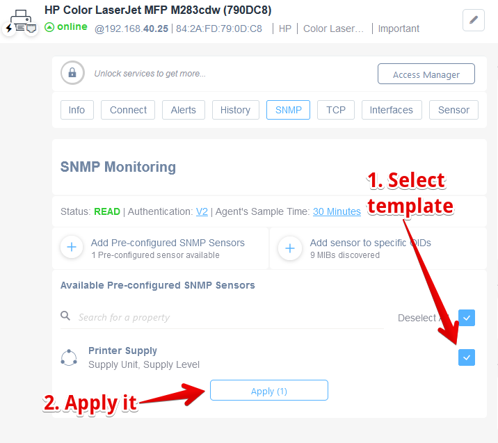
Adding and Applying Pre-configured SNMP Sensors
1. In the SNMP Monitoring section, select the template labeled "Printer Supply" by clicking the checkbox next to it, indicating it is ready for use.
2. Click the "Apply (1)" button to apply the selected printer supply template. This will configure the SNMP sensor based on the chosen template settings.
General Information
Network System Uptime
This SNMP sensor measures the network system’s uptime in days:
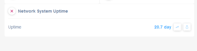
Network System Uptime Display
1. The main label "Network System Uptime" indicates the section for system uptime monitoring.
2. Below the label, the word "Uptime" is displayed.
3. To the right, the current uptime duration is shown as "20.7 day."
4. Next to the uptime duration are two icons: a graph icon for viewing uptime statistics and an arrow icon for refreshing the data.
System Uptime
This SNMP sensor measures the General System uptime in days:

System Uptime Overview
1. Title: "System Uptime" is displayed, indicating the section of the dashboard.
2. The uptime duration is shown as "75.9 days," representing how long the system has been operational without interruption.
3. Icons next to the uptime value allow users to view additional details or set alerts related to system performance.
Memory Info
This SNMP sensor template monitors the memory of a device, and extracts the following properties:
- Total Memory Installed
- Memory Available
- Memory Used (percentage)
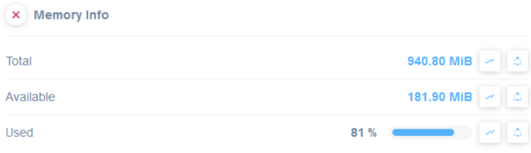
Memory Information Overview
1. **Total Memory:** Displays the total memory as 940.80 MiB.
2. **Available Memory:** Shows the available memory, which is 181.90 MiB.
3. **Used Memory:** Indicates that 81% of the memory is used, accompanied by a visual progress bar for quick reference.
Servers and Servers Controller Boards
Dell iDRAC
Two SNMP pre-configured sensors are available to monitor specific items for Dell iDRAC management platform:
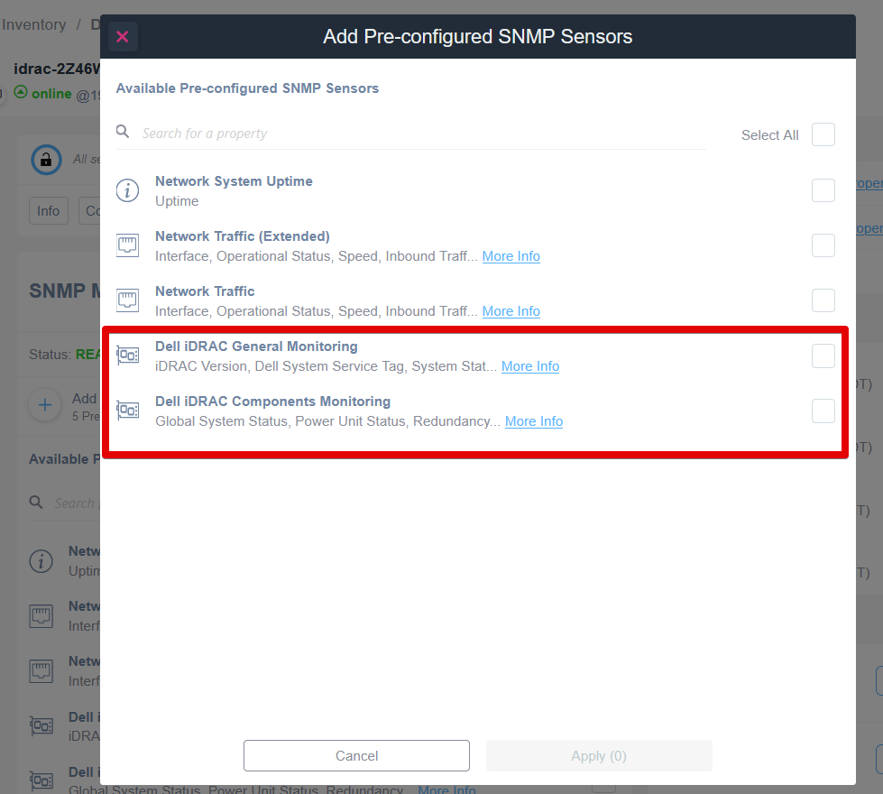
Add Pre-configured SNMP Sensors in Monitoring Software
1. In the "Add Pre-configured SNMP Sensors" dialog, browse the list under "Available Pre-configured SNMP Sensors."
2. Locate and review options for "Dell iDRAC General Monitoring" for details like iDRAC Version and System Status. Click "More Info" for further details.
3. Consider "Dell iDRAC Components Monitoring" for monitoring Global System and Power Unit Status. Click "More Info" for additional information.
4. Select the checkboxes next to the desired monitoring options to add them.
5. Finalize your selection by clicking "Apply" or "Cancel" if no changes are needed.
General Monitoring
In case of a Dell iDRAC management platform, an SNMP pre-configured template is available to extract the following general properties:
- iDRAC Version
- Dell System Service Tag
- System Status
- Storage Status
- Power State Unit Status
- LCD Status
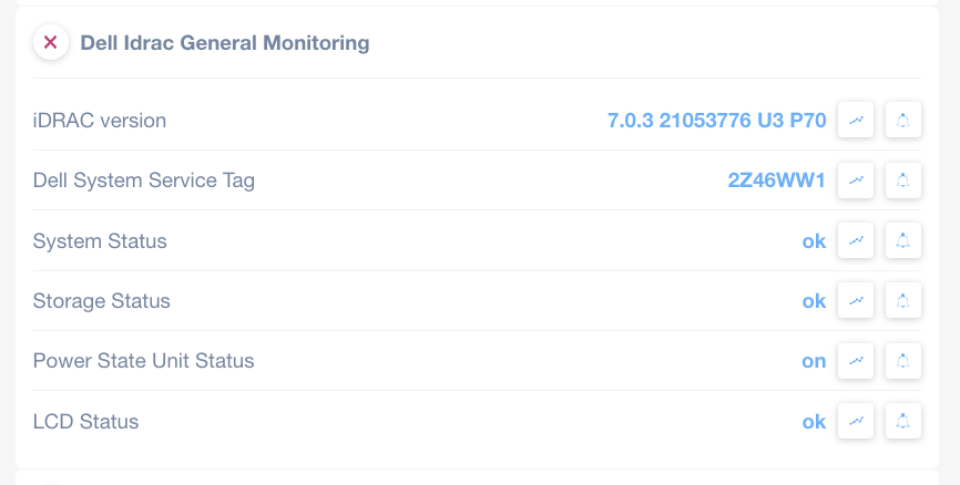
Dell iDRAC General Monitoring Overview
1. iDRAC Version: Displays the version as "7.0.3 21053776 U3 P70." Use this information to verify compatibility or troubleshoot.
2. Dell System Service Tag: Shows the service tag "2Z46WW1," necessary for warranty checks and support requests.
3. System Status: Indicates "ok," confirming the system is operating normally.
4. Storage Status: Reflects "ok," signifying that storage components are functioning correctly.
5. Power State Unit Status: Listed as "on," verifying that the power supply is active.
6. LCD Status: Displays "ok," indicating the LCD is in good condition.
Monitor these parameters regularly to ensure optimal system performance.
Components Status Monitoring
The “Dell iDRAC Components Status Monitoring” is also available.
This template will allow to monitor for each component of the system the following properties:
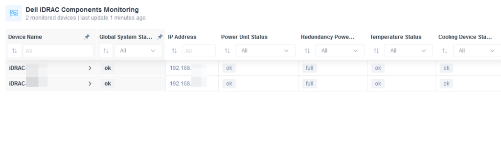
Dell iDRAC Components Monitoring Dashboard
1. The dashboard lists monitored devices with parameters for each: Device Name, Global System Status, IP Address, Power Unit Status, Redundancy Power, Temperature Status, and Cooling Device Status.
2. Each device entry shows a name and an associated IP address.
3. Status columns such as Global System Status, Power Unit Status, Temperature Status, and Cooling Device Status display the current state, typically "ok."
4. The Redundancy Power column indicates "full" for active redundancy.
5. Use this overview to quickly check device health and performance.
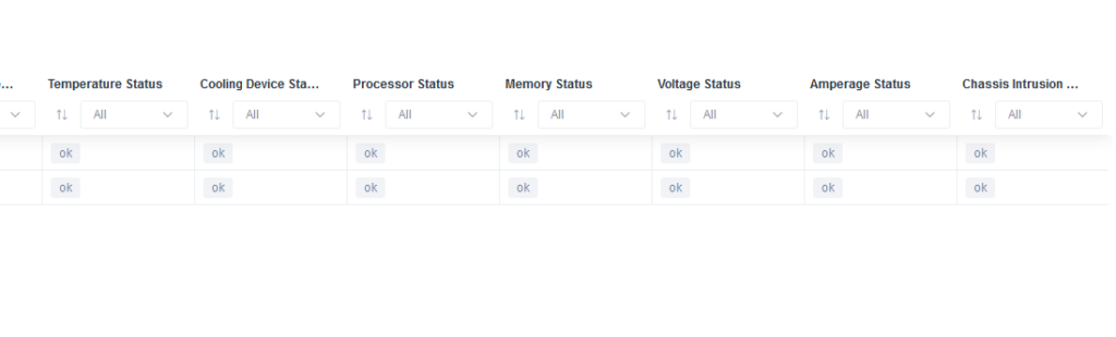
Server Health Status Overview:
1. Temperature Status: Displays temperature status, currently set to "ok."
2. Cooling Device Status: Indicates cooling device status, shown as "ok."
3. Processor Status: Lists processor health, marked as "ok."
4. Memory Status: Shows memory condition, currently "ok."
5. Voltage Status: Displays voltage status, shown as "ok."
6. Amperage Status: Lists amperage condition, marked as "ok."
7. Chassis Intrusion Status: Indicates whether chassis intrusion is detected, currently "ok."
Each status can be sorted or filtered using dropdown menus to refine the view.
HP-ILO
Six SNMP pre-configured templates are available to monitor specific items for HP-ILO platform:
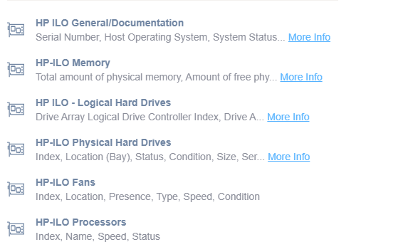
Overview of HP iLO Components and Information Access
1. HP iLO General/Documentation: Includes details such as serial number, host operating system, and system status. Click "More Info" for additional documentation.
2. HP iLO Memory: Displays total physical memory and the amount of free physical memory. Use the "More Info" link for further details.
3. HP iLO - Logical Hard Drives: Provides information on drive array logical drive controller index and drive attributes. Access more data with the "More Info" link.
4. HP iLO Physical Hard Drives: Contains details about index, bay location, status, condition, size, and serial number.
5. HP iLO Fans: Lists index, location, presence, type, speed, and condition of fans.
6. HP iLO Processors: Shows information such as index, name, speed, and status of processors.
General Documentation
For general insights and for documentation purposes, the HP ILO General/Documentation SNMP template is able to extract the following info:
- Serial Number
- Host Operating System
- System Status
- File System Status
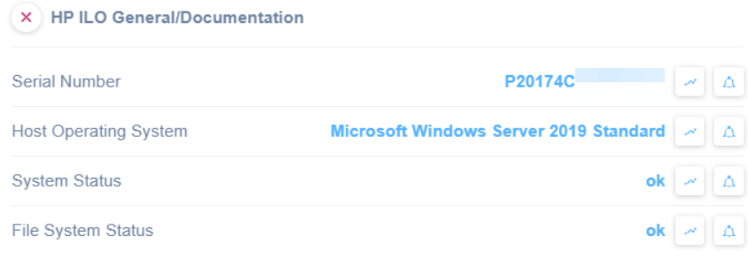
HP ILO General Documentation Interface Overview
1. Find the serial number next to "Serial Number" for device identification.
2. Check the host operating system under "Host Operating System," shown here as "Microsoft Windows Server 2019 Standard."
3. View the system status labeled "ok" under "System Status" to confirm system health.
4. Verify the file system status labeled "ok" under "File System Status" for file integrity.
Memory
In regards to memory details and health, the HP iLO Memory SNMP template is able to extract the following info:
- Physical Memory Size
- Free Physical Memory
- Paging Memory Size
- Free Paging Memory
- Fault Tolerance Protection System
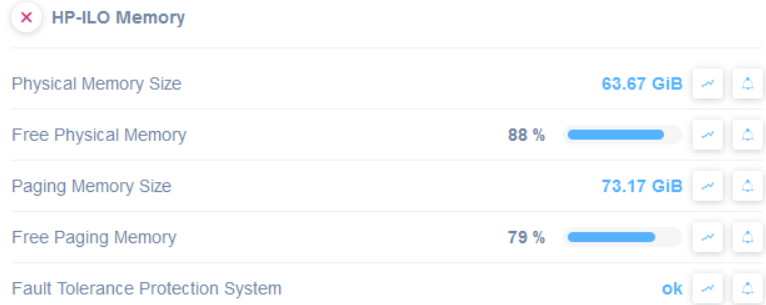
HP-ILO Memory Status Overview
1. Physical Memory Size is displayed as 63.67 GiB.
2. Free Physical Memory shows 88% availability with a progress bar indicating usage.
3. Paging Memory Size is listed as 73.17 GiB.
4. Free Paging Memory is at 79% availability with a progress bar indicating usage.
5. Fault Tolerance Protection System status is shown as "ok."
Logical Hard Drives
In regards to logical hard drivers details and health, the HP iLO Logical HD Table SNMP template is able to extract the following info:
- Drive Array Logical Drive Controller Index
- Drive Array Logical Drive Index
- Logical Drive Status
- Logical Drive condition
- Logical Drive Fault Tolerance
- Logical Drive Size

HP ILO Logical Hard Drives Monitoring Interface
1. The interface displays monitoring information for logical hard drives on an HP ILO system.
2. The column for "Device Name" shows the device identifier as "HOST6-ILO.imagebuilding.it."
3. "Drive Array Logical Drives" indicates a value of "0," and "Type" shows an icon representing a specific drive type.
4. "Drive Array Logica" and "Logical Drive Status" fields both have a value of "ok," indicating normal status.
5. "Logical Drive Condition" is marked as "ok," and "Logical Drive Fault Tolerance" shows "distribDataGuard," suggesting data protection mechanism.
6. "Logical Drive Size" is displayed as "2.62 TiB," providing the storage capacity of the drive.
Physical Hard Drives
In regards to physical hard drivers details and health, the HP iLO Physical HD Table SNMP template is able to extract the following info:
- index
- Location (bay)
- Status
- Condition
- Size
- Serial Number
- Age
- Model
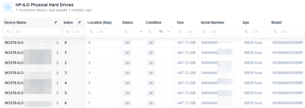
HP-ILO Physical Hard Drives Overview
1. The table lists information about physical hard drives associated with the HP-ILO system.
2. Columns include Device Name, Index, Location (Bay), Status, Condition, Size, Serial Number, Age, and Model.
3. All devices listed share the name "HOST6-ILO".
4. The Index column ranges from 0 to 6, with corresponding Location (Bay) numbers ranging from 4 to 10.
5. The Status for each device is "ok", indicating normal operation.
6. Each device has a Size of 447.13 GiB and shares similar serial numbers starting with "S4NANA0".
7. All devices have an Age of 18835 hours.
8. The Model for each drive is "VK000480GWSRR".
Fans
In regards to fans details and health, the HP iLO Fans SNMP template is able to extract the following info:
- Index
- Location
- Presence
- Type
- Speed
- Condition
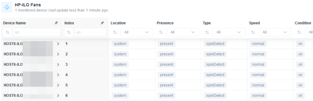
Monitoring HP-ILO Fans Status
1. The table displays information about HP-ILO fans for one monitored device, with the last update less than one minute ago.
2. Columns include Device Name, Index, Location, Presence, Type, Speed, and Condition.
3. Device Name lists entries starting with "HOST6-ILO," followed by specific identifiers.
4. Index numbers fans sequentially from 1 to 6.
5. Location is consistently labeled as "system" for all entries.
6. Presence indicates "present" for each fan.
7. Type shows "spinDetect" for all fans.
8. Speed is "normal" across all entries.
9. Condition is marked as "ok" for every fan listed.
Processors
In regards to fans details and health, the HP iLO Processors is able to extract the following info:
- Index
- Name
- Speed
- Status
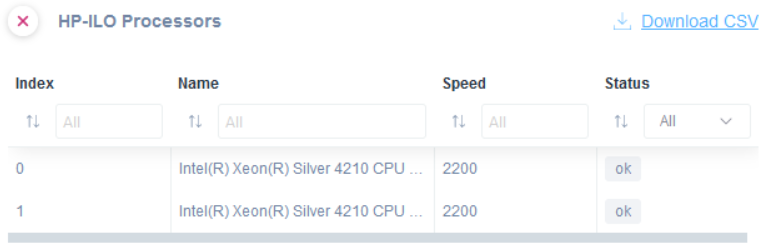
HP-ILO Processors Management Table
1. The table lists processor details with columns labeled Index, Name, Speed, and Status.
2. Each row represents a processor. For example, row 0 lists an Intel(R) Xeon(R) Silver 4210 CPU at 2200 MHz with an "ok" status.
3. The table allows filtering inputs under each column label for more specific searches.
4. A "Download CSV" link is available to export the table data.
Supermicro
General/Documentation
In case of a Supermicro server board, an SNMP pre-configured template is available to retrieve and show the following information:
- Serial Number
- BIOS Version
- BMC Major Version
- BMC Minor Version
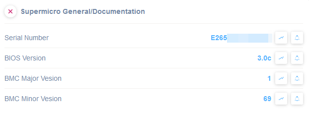
Supermicro System Information Overview
1. The "Serial Number" section displays an alphanumeric code labeled as "E265" followed by a blurred section, representing the unique identifier for the device.
2. The "BIOS Version" is listed as "3.0c," indicating the current version of the BIOS software.
3. The "BMC Major Version" is marked as "1," showing the major version number of the Baseboard Management Controller.
4. The "BMC Minor Version" is set to "69," providing the minor version number of the BMC.
Each entry is accompanied by icons for further actions, typically viewing more details or adjusting settings.
Power Supply Units
In case of a Supermicro server board, an SNMP pre-configured template is available to monitor its Power Supply Units status:
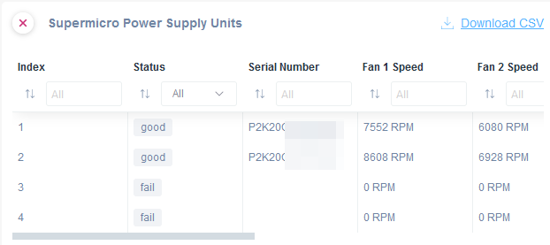
Dashboard for Monitoring Supermicro Power Supply Units
1. The dashboard displays a table of power supply units with columns: Index, Status, Serial Number, Fan 1 Speed, and Fan 2 Speed.
2. The Status column indicates the condition of each unit, showing "good" for operational units and "fail" for non-operational ones.
3. The Serial Number column contains unique identifiers for each unit, partially obscured for privacy.
4. The Fan 1 Speed and Fan 2 Speed columns show the rotational speed in RPM. Units with a "fail" status have a speed of 0 RPM for both fans.
5. Above the table, there's an option to download the data as a CSV file for further analysis or record keeping.
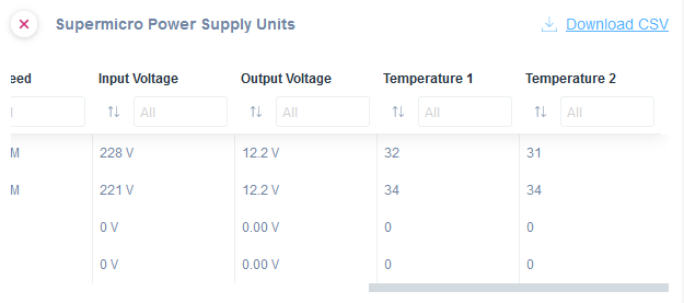
Power Supply Units Monitoring Table
1. The table displays details of Supermicro power supply units.
2. Columns include Input Voltage, Output Voltage, Temperature 1, and Temperature 2.
3. Each column header allows sorting and filtering options.
4. First and second units show input voltages of 228 V and 221 V, both outputting 12.2 V.
5. Temperature 1 for these units reads 32 and 34 degrees respectively, with Temperature 2 showing 31 and 34 degrees.
6. Two additional units have 0 V input and output, with temperatures recorded as 0.
7. A "Download CSV" link is available for exporting the table data.
Printers
Printer Supplies Table
This contains Supply Units (Toner Cartridge, Drum Unit) and Supply Level:
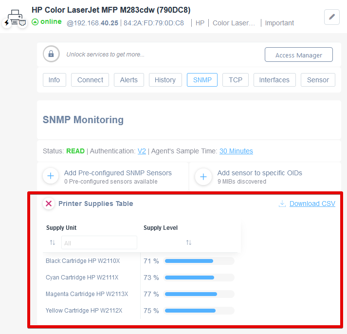
SNMP Monitoring and Printer Supplies Table
1. The interface is for an HP Color LaserJet MFP M283cdw with SNMP monitoring.
2. The printer is online, with its IP address displayed as 192.168.40.25.
3. The SNMP monitoring section shows the status as "READ" and uses Authentication V2.
4. In the "Printer Supplies Table," there are records for four cartridges:
- Black Cartridge HP W2110X: 71% supply level.
- Cyan Cartridge HP W2111X: 73% supply level.
- Magenta Cartridge HP W2113X: 77% supply level.
- Yellow Cartridge HP W2112X: 75% supply level.
5. There is an option to download the printer supplies data as a CSV file.
Printer Serial Number
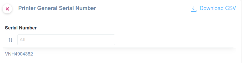
Printer Serial Number Information Interface
1. The interface is titled "Printer General Serial Number."
2. A "Serial Number" search bar is shown with a placeholder text "All."
3. Below the search bar, a specific serial number, "VNH4904382," is displayed.
4. To the top right, there is an option to download the information as a CSV file by clicking "Download CSV."
Once applied and done, you can remove the SNMP template since the serial number will be shown in the Domotz Info tab.
Brother Printer Status
Monitor the status of a Brother printer:

Brother Printer Status Display
1. The section displays the status of a Brother printer.
2. A red circle with an 'X' indicates an issue with the printer.
3. Below, the word "Status" is followed by the color "green" in blue text, suggesting a normal or operational state.
4. Additional icons are present for expanded details or notifications.
Printer Detected Error State
Monitor the status of a printer:
- Low Paper
- No Paper
- Low Toner
- No Toner
- Door Open
- Jammed
- Offline
- Service Requested
- Input Tray Missing
- Output Tray Missing
- Marker Supply Missing
- Output Near Full
- Output Full
- Input Tray Empty
- Overdue Prevent Maint
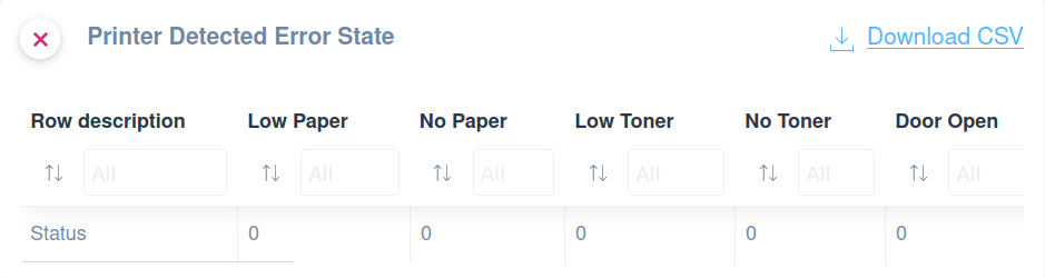
Printer Error Status Overview
1. The page displays the current error state of a printer.
2. The main headings include: Row Description, Low Paper, No Paper, Low Toner, No Toner, and Door Open.
3. Each column has a filter option where you can select specific error types via a dropdown labeled "All."
4. The Status row shows zero for all error types, indicating no current issues.
5. There is an option to download the error report as a CSV file via the "Download CSV" link at the top right.
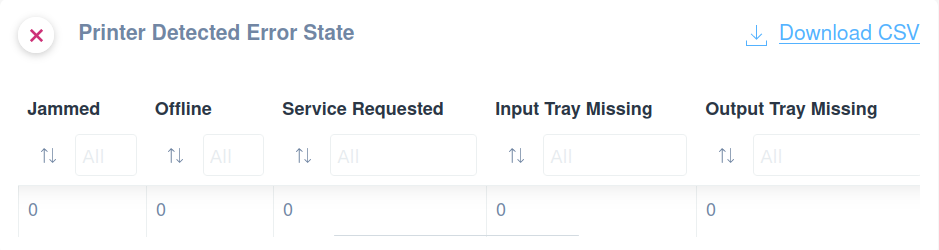
Printer Error Status Dashboard
1. The dashboard displays the error status of printers under the title "Printer Detected Error State."
2. Categories shown include Jammed, Offline, Service Requested, Input Tray Missing, and Output Tray Missing.
3. Each category has a corresponding text field that defaults to "All" and a numeric value below it. Currently, all categories display the value "0," indicating no errors.
4. A "Download CSV" link is available to export the error data. Use this option for offline analysis or record-keeping.
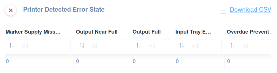
Printer Error State Overview Table
1. The top left indicates "Printer Detected Error State" with an option to dismiss the notification.
2. Columns display various error categories: "Marker Supply Miss...," "Output Near Full," "Output Full," "Input Tray E...," and "Overdue Prevent...".
3. Each column has a filter option set to "All" by default, allowing you to filter by specific error occurrences.
4. The bottom row shows the count of errors, with all columns currently indicating '0'.
5. A "Download CSV" option is available in the top right for exporting the data.
UPS
For UPS devices, the UPS Basic Info template is available.
This template contains Alarms Present, Battery Status, Battery Voltage, Battery Current, Battery Temperature, Estimated Remaining Minutes, Estimated Remaining Charge and Output Source:
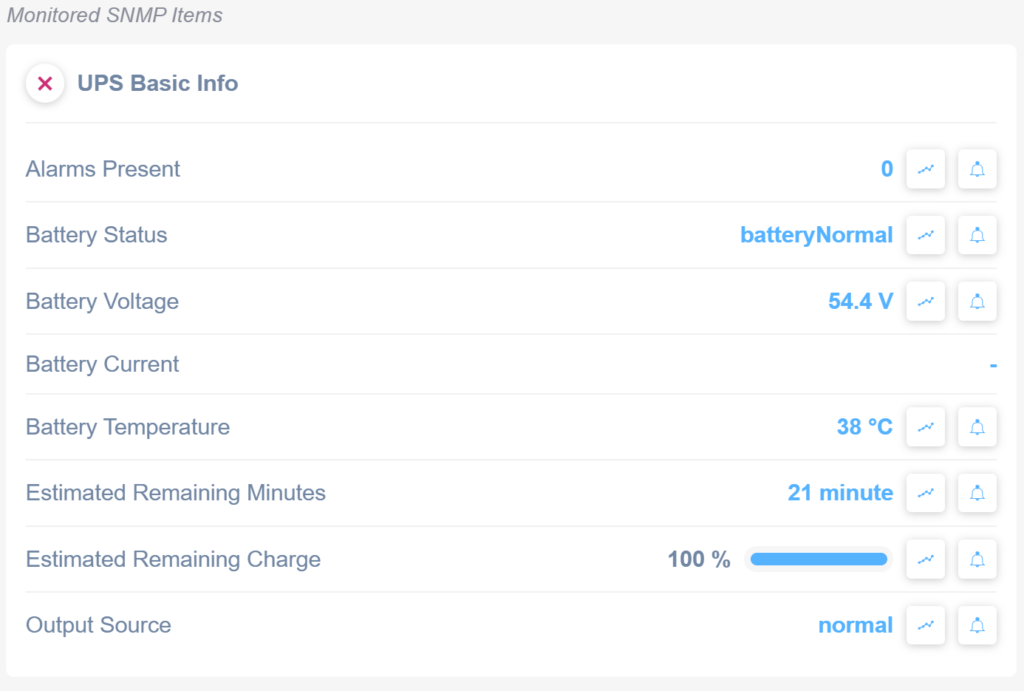
UPS Basic Info Panel Summary
1. Alarms Present: Displays the number of active alarms, currently showing 0.
2. Battery Status: Indicates the status of the battery, labeled as "batteryNormal."
3. Battery Voltage: Shows the battery voltage, currently at 54.4 V.
4. Battery Current: Displays the battery current, which is not specified.
5. Battery Temperature: Shows the temperature of the battery, currently 38°C.
6. Estimated Remaining Minutes: Indicates the estimated time remaining, showing 21 minutes.
7. Estimated Remaining Charge: Displays the charge percentage, currently at 100%.
8. Output Source: Shows the output source status, labeled as "normal."
Each line includes additional graph and notification icons for further actions.
Cyberpower UPS General
For Cyberpower UPS we do have a specific SNMP template which allows to monitor the following:
- Battery Last Replaced Date
- Recommended Battery Life (time remaining)
- Environment Temperature in C and F
- Environment Humidity
- Battery Replace Indicator
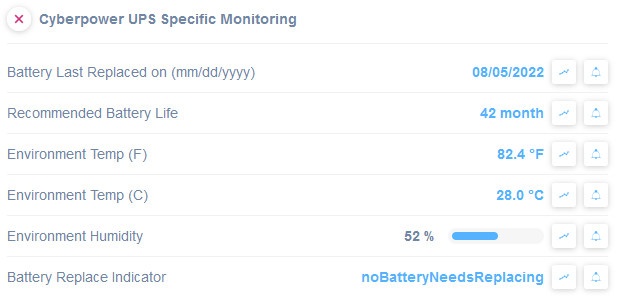
Cyberpower UPS Monitoring Dashboard
1. Check when the battery was last replaced, displayed as "08/05/2022."
2. Note the recommended battery life, listed as "42 months."
3. Observe the environmental temperature in Fahrenheit, shown as "82.4 °F."
4. View the environmental temperature in Celsius, indicated as "28.0 °C."
5. Assess the environment humidity, presented as "52%."
6. Review the battery replacement status with "noBatteryNeedsReplacing," indicating no replacement is currently needed.
APC UPS Replacement Dates
For APC UPS we do have a specific SNMP template which allows to monitor the following:
- Battery Last replaced date
- Battery recommended replacement date
- Remaining days for battery replacement
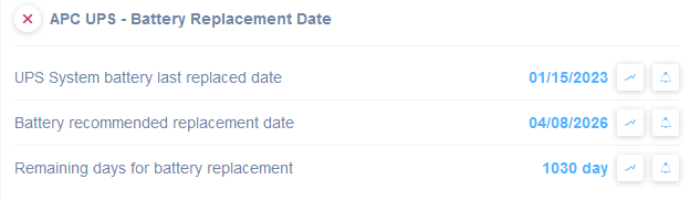
APC UPS Battery Replacement Information
1. UPS System battery last replaced date is January 15, 2023.
2. Battery recommended replacement date is April 8, 2026.
3. Remaining days for battery replacement are 1030 days.
Innovolt UPS
General Info
The General Info template shows the following metrics:
- Protocol id
- Model name
- Serial number
- Firmware version
- UPS type
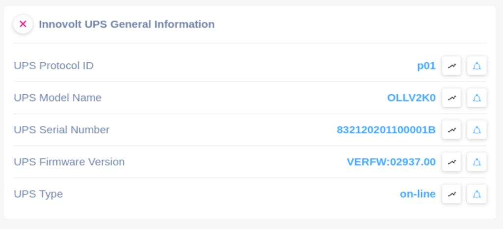
Innovolt UPS General Information Display
1. The "UPS Protocol ID" is listed as "p01."
2. The "UPS Model Name" is identified as "OLLV2K0."
3. The "UPS Serial Number" is displayed as "832120201100001B."
4. The "UPS Firmware Version" is recorded as "VERFW:02937.00."
5. The "UPS Type" is shown as "on-line."
Battery Metrics
The Battery Metrics template shows the following metrics:
- Number of batteries in parallel
- Battery status
- Number of batteries in series
- Estimate of the remaining battery charge
- Estimate of the time to battery charge depletion
- The ambient temperature at or near the UPS Battery casing
- The magnitude of the present Positive battery voltage.
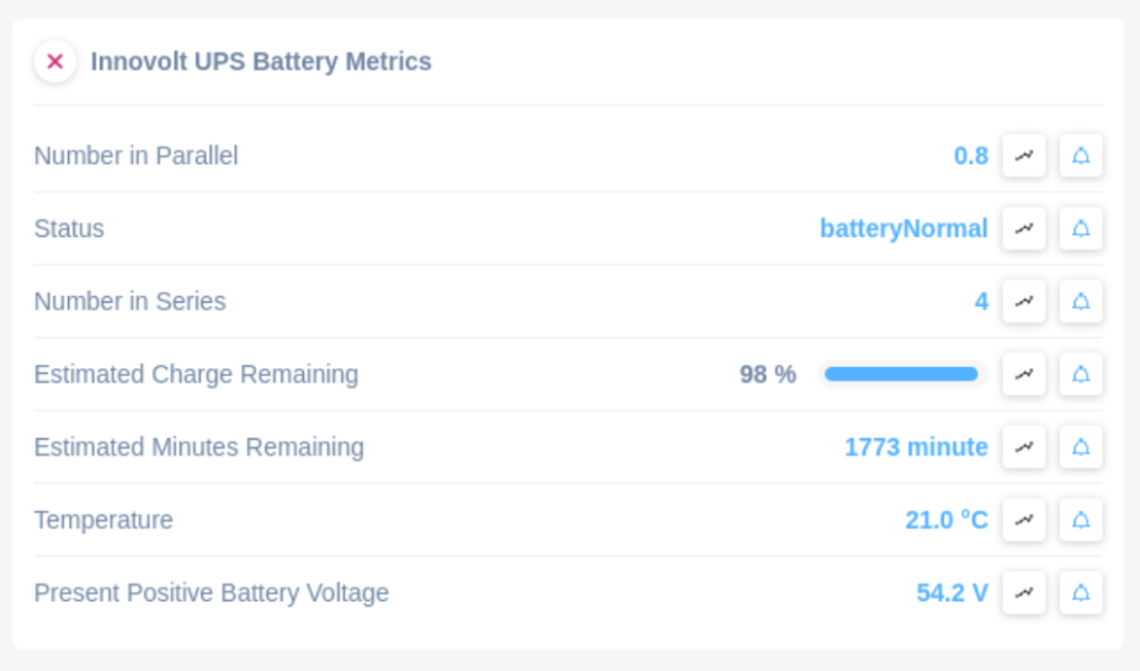
Innovolt UPS Battery Metrics Panel.
1. "Number in Parallel" displays the value 0.8.
2. "Status" shows the text "batteryNormal," indicating normal operation.
3. "Number in Series" is listed as 4.
4. "Estimated Charge Remaining" is at 98%, with a visual progress bar.
5. "Estimated Minutes Remaining" is 1773 minutes.
6. "Temperature" reads 21.0 degrees Celsius.
7. "Present Positive Battery Voltage" is 54.2 volts.
Each metric provides insights into the current state and performance of the UPS battery.
UPS Rating
The UPS Rating template shows the following metrics:
- Rated input voltage
- Rated output voltage
- Rated output frequency
- Rated output current
- Rated apparent power
- Rated true power
- Rated battery voltage
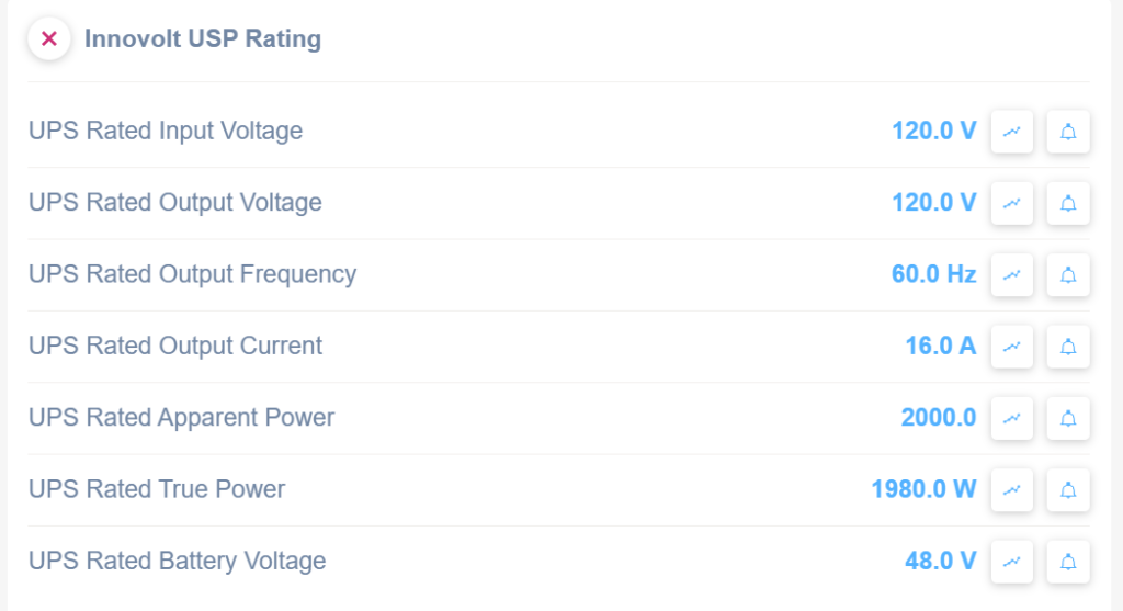
Innovolt USP Rating Overview.
1. The "UPS Rated Input Voltage" is 120.0 V.
2. The "UPS Rated Output Voltage" is also 120.0 V.
3. The "UPS Rated Output Frequency" is 60.0 Hz.
4. The "UPS Rated Output Current" is 16.0 A.
5. The "UPS Rated Apparent Power" is 2000.0.
6. The "UPS Rated True Power" is 1980.0 W.
7. The "UPS Rated Battery Voltage" is 48.0 V.
Each value is followed by icons for graph and lock functionalities.
Input Power Status
The Input Power Status template shows the following metrics:
- Input frequency
- Input utility line voltage
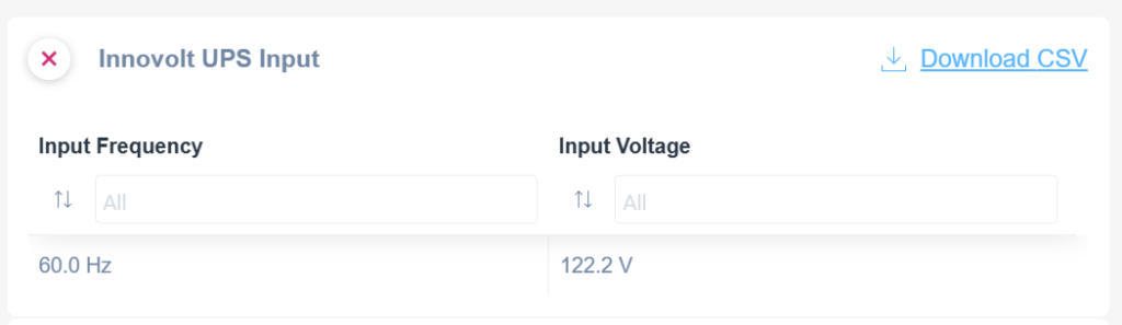
Innovolt UPS Input data display and download.
1. The "Innovolt UPS Input" section shows current measurements.
2. Two sections, "Input Frequency" and "Input Voltage," are displayed.
3. "Input Frequency" reads as 60.0 Hz.
4. "Input Voltage" reads as 122.2 V.
5. There is an option labeled "Download CSV" to download the data.
Output Power Status
The Output Power Status template shows the following metrics:
- Source of output power
- Current output frequency
- Number of Output Lines Used
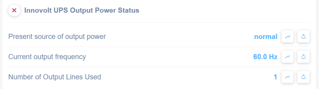
Innovolt UPS Output Power Status interface.
1. The "Present source of output power" is listed as "normal."
2. The "Current output frequency" is displayed as "60.0 Hz."
3. The "Number of Output Lines Used" shows "1."
Each entry includes icons for viewing trends and setting alerts, accessible via buttons next to each status.
Test Results
The Test Results template shows the following metrics:
- Test Result
- Test Start Time
- Test Setting Time
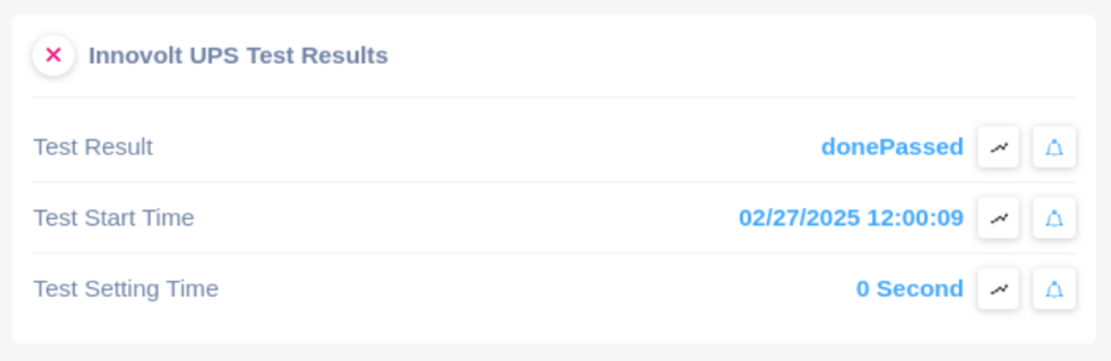
Innovolt UPS Test Results Summary
1. The "Test Result" shows the status as "donePassed," indicating the test was successful.
2. The "Test Start Time" is recorded as "02/27/2025 12:00:09," specifying when the test began.
3. The "Test Setting Time" is displayed as "0 Second," indicating no additional setting time was applied.
ByPass Mode
The Bypass Mode template shows the following metrics:
- Bypass Line Identifier
- Present bypass voltage
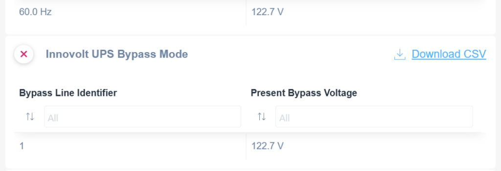
Innovolt UPS Bypass Mode Interface
1. The interface shows the "Innovolt UPS Bypass Mode" title and an option to download data as a CSV file by clicking "Download CSV."
2. Under "Bypass Line Identifier," input or view identifiers for the bypass lines. The default entry displays the identifier "1."
3. Under "Present Bypass Voltage," view or input the current voltage value. The default entry shows "122.7 V."
NAS
If the device is a NAS, three different SNMP templates are available.
NAS Hard Disk Table
The NAS Hard Disks Table template shows Hard Disks, Description, Status, Capacity, Info, Temperature, and Model:
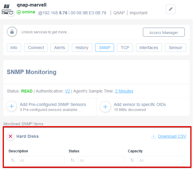
SNMP Monitoring Settings for Hard Disks
1. The interface displays a device named "qnap-marvell" with its status as online and an IP address of 192.168.5.76.
2. Access various settings via tabs, including Info, Connect, Alerts, History, SNMP, TCP, Interfaces, and Sensor. The SNMP tab is active.
3. SNMP Monitoring section shows a status of READ with authentication set to V2 and the agent's sample time as 2 minutes.
4. Options to add pre-configured SNMP sensors or add sensors to specific OIDs are available.
5. Under Monitored SNMP Items, there is a category for Hard Disks.
6. Within Hard Disks, sortable columns include Description, Status, and Capacity. Each column has input fields for filtering results.
7. An option to download the data as a CSV file is present.
NAS Volumes Table
The NAS Volumes Table template displays Volumes, Description, Free Size, Total Size, Filesystem, and Status.
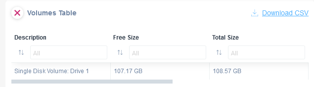
Volumes Table interface for disk information.
1. This interface lists disk volumes with details in three columns: Description, Free Size, and Total Size.
2. The "Description" column shows "Single Disk Volume: Drive 1."
3. The "Free Size" column indicates 107.17 GB of space available.
4. The "Total Size" column displays a total capacity of 108.57 GB.
5. Use the filters under each column to sort or filter the information.
6. A "Download CSV" option is available to export the table data.
NAS Basic Info
The NAS Basic Info template contains CPU Usage, CPU Temperature, Total Available Memory, Free Memory, Uptime, System Temperature, Number of Hard disks, Volumes, and Last Error Message:
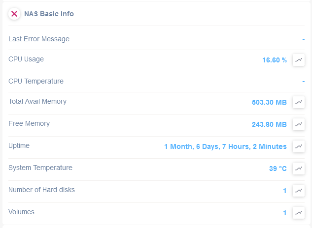
NAS Basic Information Overview
1. Last Error Message: No message available.
2. CPU Usage: Displays the current CPU usage at 16.60%.
3. CPU Temperature: No data available.
4. Total Available Memory: Shows the total memory available as 503.30 MB.
5. Free Memory: Indicates the memory currently free, which is 243.80 MB.
6. Uptime: Specifies the system has been running for 1 month, 6 days, 7 hours, and 2 minutes.
7. System Temperature: Shows the system temperature at 39°C.
8. Number of Hard Disks: Indicates there is 1 hard disk installed.
9. Volumes: Displays that there is 1 volume configured.
Note: Not all the NAS rely on the standard NAS-MIB.The current Pre-Configured SNMP template is limited to QNAP, ReadyNAS, Synology and all the NAS drives relying on the NAS-MIB.
Synology RAID Volumes:
For each RAID configured on the Synology NAS, we monitor status, usage, and available free storage. For each sensor retrieved you also get a graphical representation of the historical values.
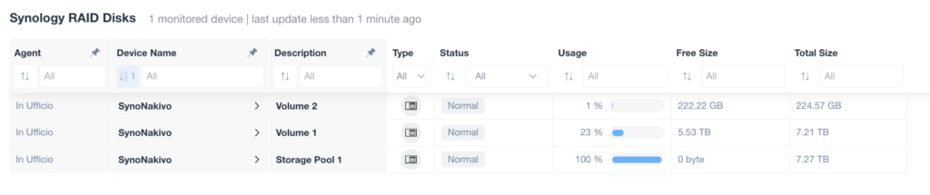
Synology RAID Disks Overview
1. The table displays information about monitored Synology RAID disks.
2. Columns include Agent, Device Name, Description, Type, Status, Usage, Free Size, and Total Size.
3. Each row represents a different volume or storage pool.
4. The Status column shows the health status, such as "Normal."
5. The Usage column indicates the percentage of disk space used.
6. The Free Size and Total Size columns display available space and overall capacity details.
7. Use the information to monitor disk health and manage storage efficiently.
Synology SMART Disks Status:
For each disk and variable of the Disk, Domotz will monitor the status of the variable and the value (for instance Airflow Temperature, Command Timeout, Pending Sector, E2E Errors, Power Cycle Counts, etc):
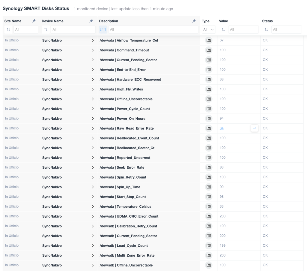
Synology SMART Disks Status Table
1. The table displays monitored disk status with columns labeled: Site Name, Device Name, Description, Type, Value, and Status.
2. Each row represents a specific disk parameter such as Airflow Temperature, Command Timeout, and Power On Hours.
3. The Value column shows the numerical status of each parameter, with most values being 100 or above, except for entries like Raw Read Error Rate which is 84.
4. The Status column reports each parameter as OK, indicating normal operation.
5. Use the table to assess disk health and performance by checking that the Status column displays OK for each parameter.
Switches
Network Interfaces
In case of a network switch (or in general, any Network Device supporting IF-MIB for the Interfaces statistics via SNMP) the “Network Interfaces Table” template contains the following columns:
Interface name, Operational Status, Inbound (Traffic, Discards, Errors), Outbound (Traffic, Discards Errors), NIC Type, Admin status, Phisical Address (MAC), MTU, Speed:
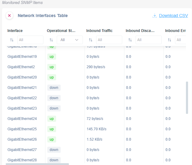
Network Interfaces Table Overview
1. The table displays a list of network interfaces with the columns: Interface, Operational Status, Inbound Traffic, Inbound Discards, and Inbound Errors.
2. Each row represents an interface, e.g., GigabitEthernet19, GigabitEthernet20, etc.
3. Operational Status indicates whether the interface is 'up' or 'down'.
4. Inbound Traffic shows the amount of incoming data, measured in bytes or KB/s.
5. Inbound Discards and Inbound Errors display any data discards or errors, typically showing '0.0'.
6. Filters are available at the top of each column to narrow results by specific criteria.
7. A "Download CSV" option is provided for exporting the table data.
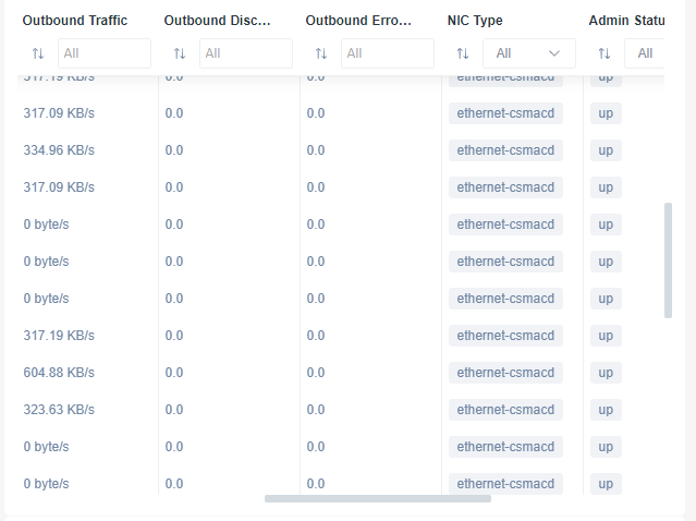
Network Interface Statistics Table
1. The table displays network statistics with columns for "Outbound Traffic," "Outbound Discards," "Outbound Errors," "NIC Type," and "Admin Status."
2. "Outbound Traffic" shows data rates like 317.19 KB/s, which can be filtered.
3. "Outbound Discards" and "Outbound Errors" display values, typically 0.0.
4. "NIC Type" lists the network interface, mostly as "ethernet-csmacd."
5. "Admin Status" indicates the current status, such as "up."
6. Use filters at the top of each column to sort and view specific data entries.
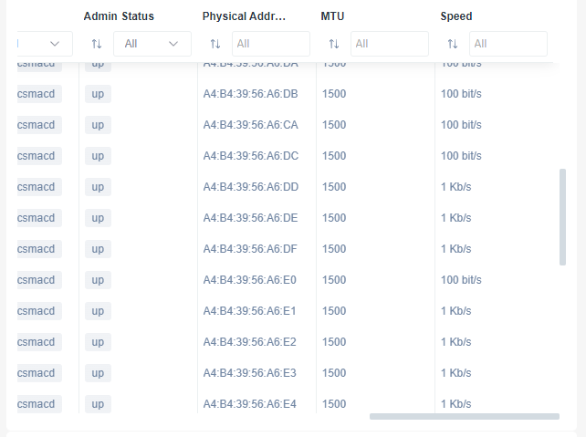
Network Interface Table Overview
1. The table displays multiple columns such as "Admin Status," "Physical Address," "MTU," and "Speed."
2. "Admin Status" shows the interface status, typically "up."
3. "Physical Address" provides the MAC address of each network interface.
4. "MTU" lists the maximum transmission unit size, here set to 1500.
5. "Speed" indicates the network speed, varying between 100 bits/s and 1 Kb/s.
6. Filters are available at the top of each column for sorting or refining the displayed data.
Bandwidth Utilization
Therefore, it is possible to also track bandwidth utilization for each switch port:
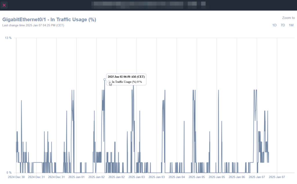
Graph of GigabitEthernet0/1 In Traffic Usage Over Time.
1. The graph displays network traffic usage in percentage over several days, from December 30, 2024, to January 7, 2025.
2. The y-axis represents traffic usage percentage, ranging from 0% to 13%.
3. The x-axis shows the timeline in days.
4. A specific data point is highlighted on January 2, 2025, at 6:50 AM (CET), indicating 9% traffic usage.
5. Options to zoom the view are available for 1 day, 7 days, and 1 month at the top right of the graph.
6. The graph updates with the last change occurring on January 7, 2025, at 4:25 PM (CET).
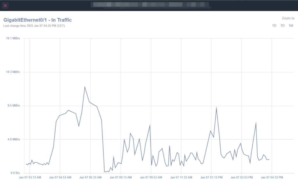
Network Traffic Graph for GigabitEthernet0/1
1. The graph displays the inbound traffic for GigabitEthernet0/1 measured in MiB/s.
2. Traffic data is plotted over time, starting from January 07 at 03:13 AM to 04:33 PM.
3. The y-axis shows traffic rates ranging from 0.0 MiB/s to 19.1 MiB/s.
4. The x-axis captures timestamps at regular intervals throughout the day.
5. Noticeable peaks occur at 06:33 AM, 01:13 PM, and 03:13 PM.
6. "Zoom to" options are available for 1 day, 7 days, or 1 month views.
7. The last change time is marked as January 07 at 04:25 PM CET. Use this to assess when the data was last updated.
FortiSwitch
General/Documentation
In case of a Fortinet FortiSwitch, an SNMP Pre-Configured template is available to extract the following general properties:
- Serial Number
- Firmware Version
- CPU usage
- Memory usage
- Hard Disk Size
- Hard Disk Usage
- Trunk Members
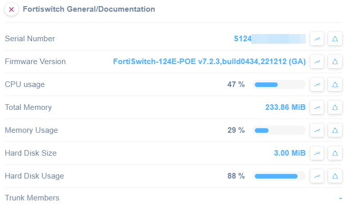
Fortiswitch System Information Overview
1. The serial number is partially displayed with the format "S124****."
2. Firmware version is "FortiSwitch-124E-POE v7.2.3, build0434, 221212 (GA)."
3. CPU usage is currently at 47%.
4. Total memory available is 233.86 MiB.
5. Memory usage is at 29%.
6. Hard disk size is listed as 3.00 MiB.
7. Hard disk usage is at 88%.
Each line provides essential hardware and performance metrics, useful for system monitoring and diagnostics.
Juniper
Serial Number
This SNMP template is really useful if you want to get the serial number of your Juniper appliances in order to synchronize it with your documentation system:

Juniper Serial Number Section in UI
1. The screen displays the "Juniper Serial Number" header.
2. Below the header, the label "Serial Number" is shown.
3. The serial number "NY0" is prominently displayed next to the label.
4. There are three interactive icons beside the serial number: one for graphs, a bell for notifications, and another icon which typically represents more options. These can be used to analyze data or manage notifications related to the serial number.
Once applied and done, you can remove the SNMP template since the serial number will be shown in the Domotz Info tab:
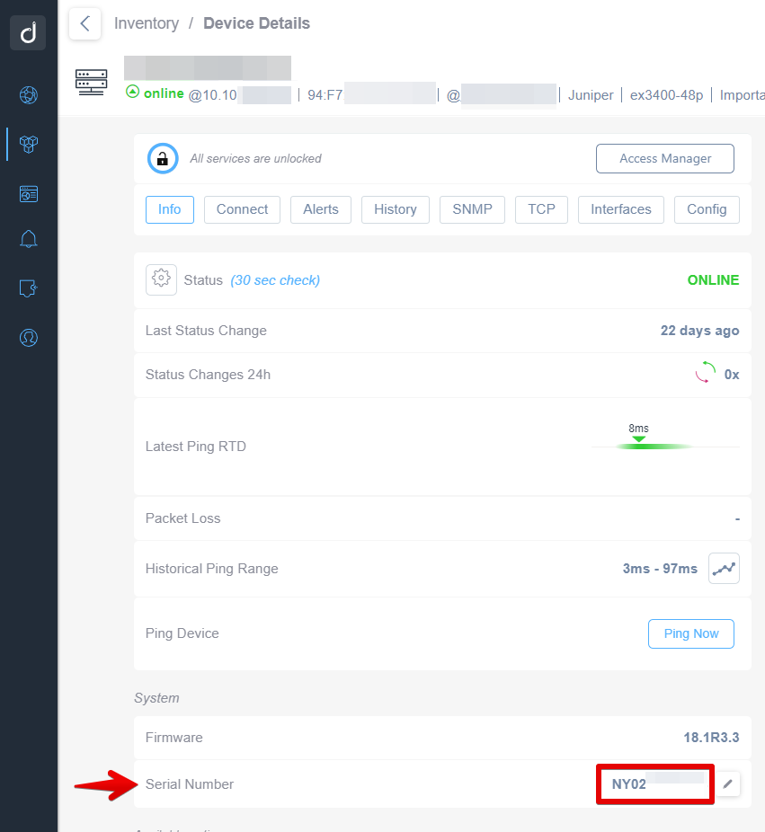
Device Details and Serial Number Location
1. At the top of the Device Details page, confirm the device is online under the status indication section, which shows "online" with a green icon.
2. Navigate through tabs like Info, Connect, Alerts, and others for specific details.
3. The device's current status is "ONLINE," with the time since the last status change noted as "22 days ago."
4. Locate key performance metrics such as Ping and Packet Loss on this interface.
5. At the bottom of the System section, find the Serial Number, highlighted as "NY02," which can be edited by clicking the pencil icon next to it.
Components Monitoring
With the ‘Juniper Components Monitoring’ SNMP template you will be able to monitor the following:
- Component Name
- CPU Usage
- Temperature
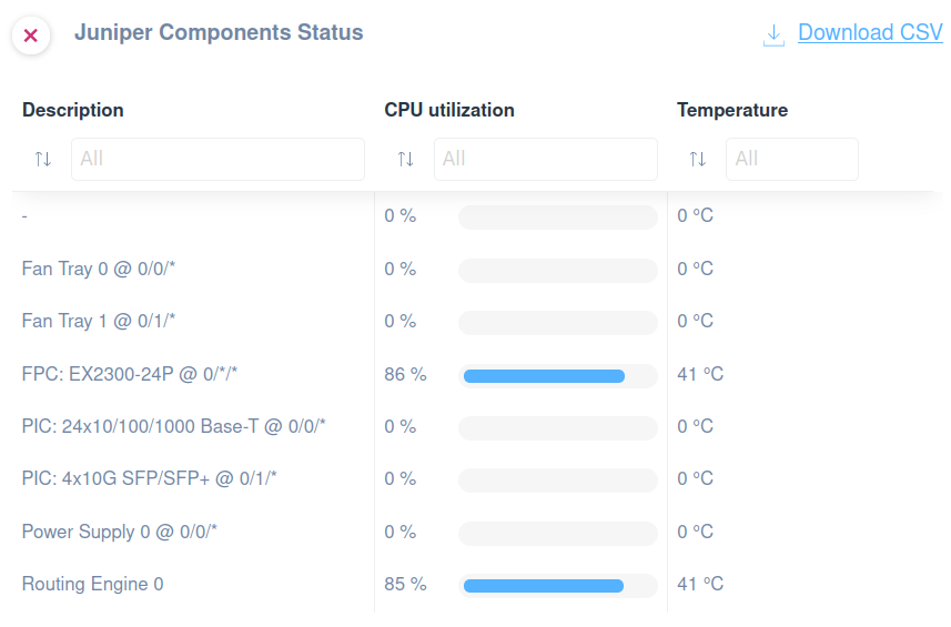
Juniper Components Status Overview
1. The table displays components' descriptions, their CPU utilization, and temperature.
2. Components include Fan Trays, FPC (EX2300-24P), PICs, Power Supply, and Routing Engine.
3. CPU utilization reaches 86% for FPC (EX2300-24P) and 85% for Routing Engine 0.
4. The temperature for both FPC and Routing Engine is 41°C.
5. Other components show 0% CPU utilization and 0°C temperature.
6. The option to download the data as a CSV file is available via a link.
Alarm
With the ‘Juniper Alerts Monitoring’ SNMP template you will be able to monitor the following:
- Yellow Alarm State
- Red Alarm State
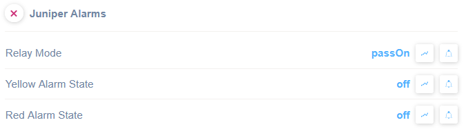
Juniper Alarms configuration interface.
1. "Relay Mode" is set to "passOn". Adjust this setting as needed to control alarm relays.
2. "Yellow Alarm State" is currently "off". Change the status to activate or deactivate the yellow alarm.
3. "Red Alarm State" is displayed as "off". Modify this setting to manage the red alarm status.
4. Each alarm state has additional options accessible via graph and settings icons to the right.
Led Table
With the ‘Juniper Led Table’ SNMP template you will be able to monitor the led indicator status listed by item:
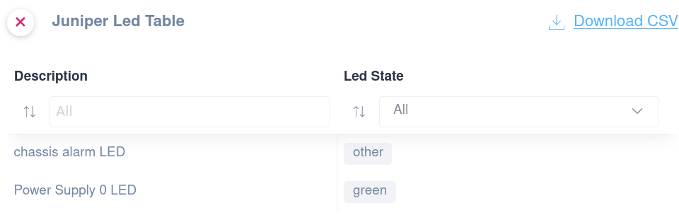
Juniper LED Table Overview
1. The table has two columns: "Description" and "Led State."
2. Under "Description," there are entries such as "chassis alarm LED" and "Power Supply 0 LED."
3. Corresponding to each description, the "Led State" column shows the states like "other" and "green."
4. Use the filters at the top of each column to sort or search the entries.
5. A "Download CSV" option is available in the top-right corner for exporting the table data.
Cisco
CPU and Memory Utilization
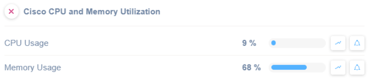
Cisco CPU and Memory Utilization Dashboard
1. The dashboard displays CPU and Memory Usage metrics for a Cisco device.
2. CPU Usage is shown at 9%, with a progress indicator.
3. Memory Usage is shown at 68%, with a progress indicator.
4. Each metric has icons to access detailed views or historical data trends.
Power Supply Monitor (CISCO-ENVMON-MIB)
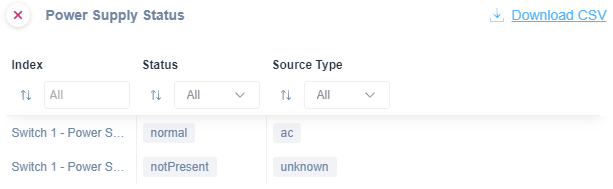
Power Supply Status Interface
1. Navigate to the "Power Supply Status" section to view the current status of power supplies.
2. Use the dropdown filters at the top to select specific criteria: "Index," "Status," and "Source Type." This allows you to filter results based on different power supply attributes.
3. The table lists each power supply item with details:
- "Switch 1 - Power Supply 1" has a status of "normal" and a source type of "ac."
- "Switch 1 - Power Supply 2" shows a status of "notPresent" and a source type of "unknown."
4. Click on "Download CSV" in the top right corner to export the displayed data to a CSV file for further analysis or record-keeping.
Possible values are:
Normal (1), Warning (2), Critical (3), Shutdown (4), Not Present (5), Not Functioning (6)
Fan Monitor (CISCO-ENVMON-MIB)
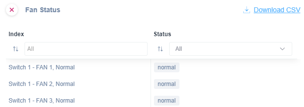
Fan Status Dashboard Overview
1. The title "Fan Status" indicates the purpose of the dashboard, which monitors fan conditions.
2. Two main columns are displayed: "Index" and "Status."
3. The "Index" column lists the fan identifiers: "Switch 1 - FAN 1," "Switch 1 - FAN 2," and "Switch 1 - FAN 3," all labeled as “Normal.”
4. The "Status" column shows "normal" for each fan, indicating their operational state.
5. Filter options are available above each column to sort or narrow down the list.
6. A "Download CSV" link at the top-right corner allows exporting the data for external use.
Possible values are:
Normal (1), Warning (2), Critical (3), Shutdown (4), Not Present (5), Not Functioning (6)
Power Supply Monitor (CISCO-ENTITY-FRU-CONTROL-MIB)
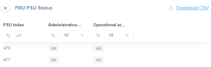
FRU PSU Status Table Overview
1. The table displays three columns: "PSU Index," "Administrative," and "Operational Status."
2. Each column header includes a sorting option and filter dropdown set to "All."
3. Under "PSU Index," entries "470" and "471" are listed.
4. In the "Administrative" and "Operational Status" columns, the status for both entries is "on."
5. A "Download CSV" option is available in the upper right corner for exporting the data.
Fan Monitor (CISCO-ENTITY-FRU-CONTROL-MIB)
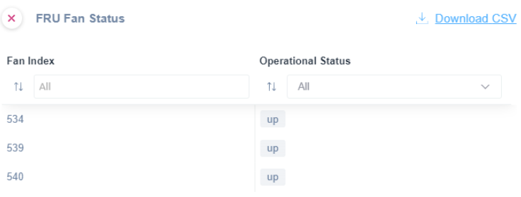
FRU Fan Status Dashboard
1. The dashboard displays a table with two columns: "Fan Index" and "Operational Status."
2. Under "Fan Index," numbers like 534, 539, and 540 are listed.
3. Corresponding to each fan index number, the "Operational Status" shows the status as "up."
4. Above the table, there are dropdown menus labeled "All" for filtering both "Fan Index" and "Operational Status."
5. A "Download CSV" link is available at the top-right corner for exporting the table data.
Possible values are:
unknown(1) – unknown, up(2) – powered on, down(3) – powered down, warning(4) – partial failure, needs replacement as soon as possible.
Ruckus
Following the SNMP Templates available for Ruckus Switches.
Serial Number
This SNMP template is really useful if you want to get the serial number of your Ruckus appliances in order to synchronize it with your documentation system:
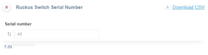
Ruckus Switch Serial Number Search and Export
1. A search bar is available under "Serial number" to filter results by entering a specific serial number or selecting "All" to view all entries.
2. The "Download CSV" option allows you to export the list of serial numbers to a CSV file.
3. The list of serial numbers begins below the search bar, with "FJN" displayed as a sample entry.
Once applied and done, you can remove the SNMP template since the serial number will be shown in the Domotz Info tab.
CPU and Memory Usage
An SNMP Pre-Configured template is available to extract the following properties:
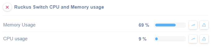
Ruckus Switch CPU and Memory Usage Dashboard
1. Memory Usage: Displayed as 69%, with a visual progress bar indicating current consumption.
2. CPU Usage: Displayed as 9%, accompanied by a smaller progress bar.
3. Graph and alert icons: Adjacent to each usage figure, allowing users to access detailed performance graphs or set alerts for each metric.
Power Supply Units
For PSU, an SNMP Pre-Configured template is available to extract the following properties:
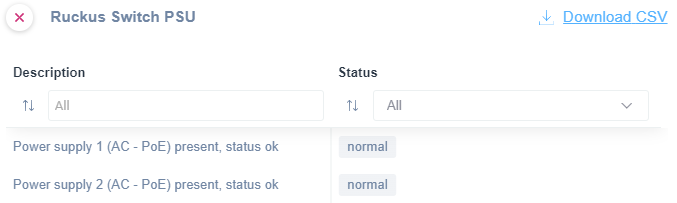
Ruckus Switch PSU Status Overview
1. The header displays "Ruckus Switch PSU" with an option to download the information as a CSV file.
2. Two columns labeled "Description" and "Status" are present.
3. In the "Description" column, entries for "Power supply 1 (AC - PoE) present, status ok" and "Power supply 2 (AC - PoE) present, status ok" are listed.
4. In the "Status" column, both entries show "normal," indicating that the power supplies are functioning correctly.
Fans
For Fans, an SNMP Pre-Configured template is available to extract the following properties:
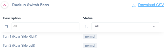
Ruckus Switch Fans Status Display
1. The interface displays two columns: "Description" and "Status."
2. Under "Description," two fans are listed: "Fan 1 (Rear Side Right)" and "Fan 2 (Rear Side Left)."
3. The "Status" for both fans shows as "normal."
4. There is a "Download CSV" option available in the top right corner for exporting data.
Dell
EMC Switch General/Monitoring
In case of Dell EMC Switch, an SNMP Pre-Configured template is available to extract the following properties:
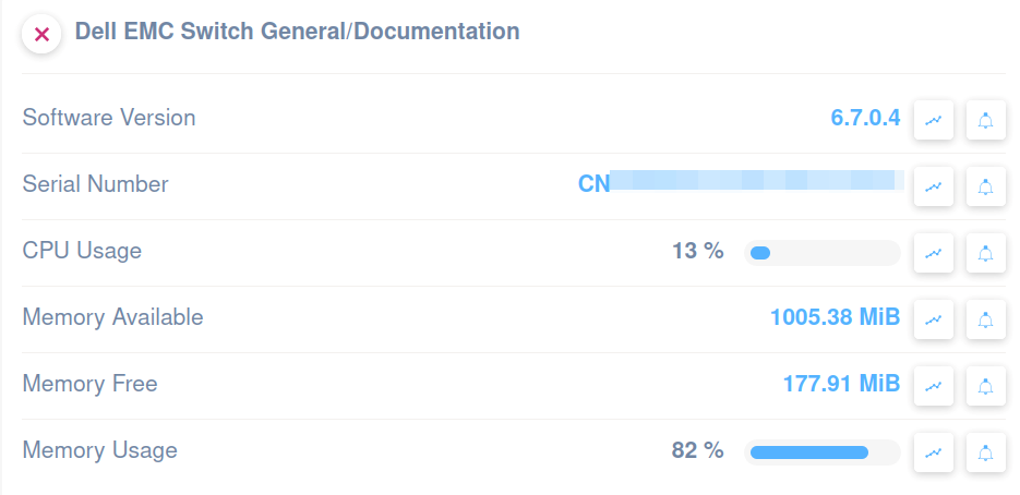
Dell EMC Switch General Information Panel
1. Software Version is displayed as 6.7.0.4.
2. Serial Number is partially obscured for privacy.
3. CPU Usage shows a value of 13%.
4. Memory Available indicates 1005.38 MiB.
5. Memory Free is shown as 177.91 MiB.
6. Memory Usage is indicated at 82%.
EMC Switch Power Supply Units
For PSUs, an SNMP Pre-Configured template is available to extract the following properties:
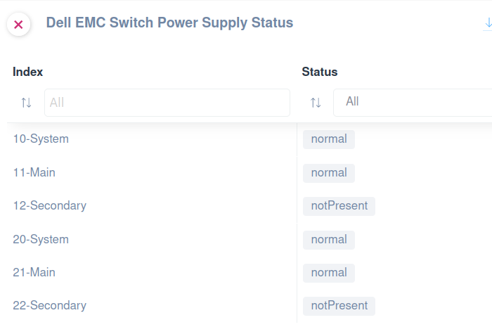
Dell EMC Switch Power Supply Status Overview
1. The screen displays a list of power supplies with their current status.
2. Each power supply is identified by an "Index" number and a "System" label (e.g., 10-System, 11-Main).
3. The "Status" column indicates whether each power supply is "normal" or "notPresent".
4. Filter options are available at the top for both "Index" and "Status" columns to refine the list.
5. Use this information to monitor and assess the functionality of the power supplies in the system.
EMC Switch Fans
For fans, an SNMP Pre-Configured template is available to extract the following properties:
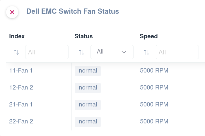
Dell EMC Switch Fan Status Table Overview
1. The table displays fan status information for a Dell EMC switch.
2. The columns are labeled: Index, Status, and Speed.
3. The "Index" column lists fans identified as "11-Fan 1," "12-Fan 2," "21-Fan 1," and "22-Fan 2."
4. The "Status" column indicates all fans are functioning normally.
5. The "Speed" column shows each fan's speed at 5000 RPM.
6. Filters are available above the column labels to sort or specify criteria for "Index," "Status," and "Speed."
Wi-Fi Equipment
Ruckus Wi-Fi Access Point
General Monitoring
In case of Ruckus Access Point, an SNMP Pre-Configured template is available to extract the following properties:
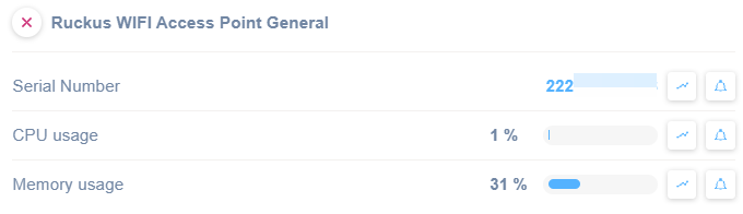
Ruckus WIFI Access Point Status Overview.
1. The serial number of the device is displayed as "222."
2. CPU usage is shown as "1%," indicating low processing activity.
3. Memory usage registers at "31%," with a partially filled bar representing usage visually.
These details help monitor the performance of the access point, useful for troubleshooting or performance assessment.
Firewalls
WatchGuard
General Info
In case of WatchGuard Firewall, an SNMP Pre-Configured template is available to extract the following properties:
- SysA Software Version
- SysB Software Version
- CPU Utilization
- Memory unused/available
- Currently Active Connections
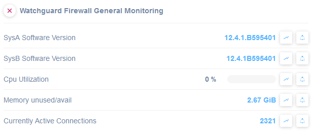
Watchguard Firewall General Monitoring Overview
1. Check the software version details: SysA is version 12.4.1.B595401 and SysB is also version 12.4.1B595401.
2. Monitor the CPU utilization, which is currently at 0%.
3. Examine memory status where 2.67 GiB is unused or available.
4. Note the number of currently active connections, totaling 2321.
Use these details to assess system performance and detect potential issues.
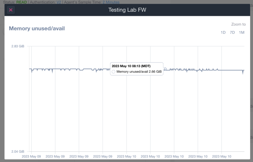
Graph of Memory Usage Over Time
1. The graph tracks memory unused/available in gigabytes (GiB) over time.
2. The vertical axis represents memory available, ranging from 2.04 GiB to 2.83 GiB.
3. The horizontal axis shows the timeline from May 9, 2023, to May 10, 2023, with date markers.
4. A data point on May 10, 2023, at 08:13 MDT, shows 2.66 GiB of memory available.
5. Zoom options on the right allow adjusting the view to 1 Day, 7 Days, or 1 Month to see different data ranges.
Policies Monitoring
The “WatchGuard Firewall Policies” is also available.
This template will allow to monitor for each defined Policy the following properties:
- Discarded Packets rate (#/s) (number of packets discarded per second)
- Logging (indicates whether if the logging of this policy has been enabled or not)
- Currently Active Connections (total number of currently active connections for the policy)
- Tunnels rate (#/s) (number of tunnels belonging to the policy per second)
- Traffic (traffic in bytes per second)
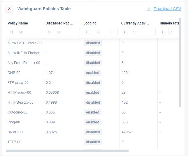
Watchguard Policies Table Overview
1. The table displays a list of policies with columns for Policy Name, Discarded Packets, Logging, Currently Active, and Tunnels Rate.
2. "Policy Name" includes entries like "Allow L2TP-Users-00" and "DNS-00."
3. "Discarded Packets" shows values such as 0.03608 for "HTTP-proxy-00" and 3.339 for "Ping-00."
4. "Logging" indicates the status, either "enabled" or "disabled," for each policy. For example, "DNS-00" is enabled, while "Allow-IKE-to-Firebox" is disabled.
5. "Currently Active" lists active instances, such as "132" for "HTTPS-proxy-00" and "1201" for "DNS-00."
6. "Tunnels Rate" is not populated with values and displays a dash (-) for all policies.
7. A "Download CSV" option is available for exporting the table data.
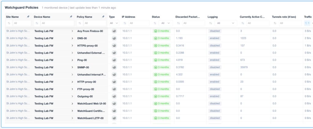
Watchguard Policies Overview
1. The table displays a list of Watchguard policies for a monitored device with columns including Site Name, Device Name, Policy Name, Type, IP Address, Status, Discarded Packets, Logging, Currently Active Connections, Tunnels Rate, and Traffic Rate.
2. The Site Name and Device Name columns show "St John's High School" and "Testing Lab FW" respectively for all entries.
3. Policy Name lists various security policies such as Any From Firebox-00, DNS-00, and HTTP-proxy-00.
4. The Type column has entries like "Any" and "Ping-00" while the IP Address column shows "10.0.1.1".
5. Status indicates how recent the updates are, marked as "3 months".
6. Discarded Packets shows specific values like 0.0 and 0.3416.
7. The Logging column specifies whether logging is "enabled" or "disabled".
8. Currently Active Connections include numeric values like 3 and 1223.
9. Tunnels Rate and Traffic Rate columns display numbers indicating network activity, such as 0.0 and 2 B/s.
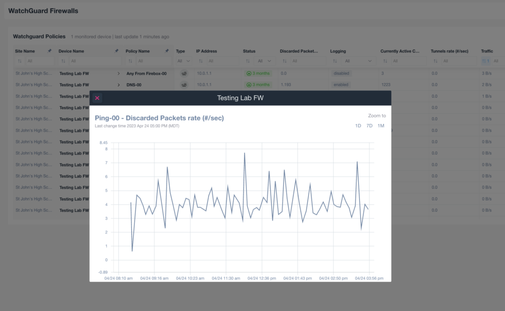
Monitoring Firewall Packet Discard Rate Over Time
1. Open the WatchGuard Firewalls interface. Identify the policies for the device named "Testing Lab FW."
2. Focus on the "Ping-00 - Discarded Packets rate (#/sec)" window. This graph displays the rate of discarded packets over a timeline.
3. Observing the graph, note fluctuations in the discarded packets rate at different times of the day.
4. Use the "Zoom to" option in the upper right corner to adjust the graph's time frame to 1 day (1D), 7 days (7D), or 1 month (1M) to analyze different periods.
5. Use this graph to monitor network stability and diagnose potential firewall issues by evaluating packet loss trends.
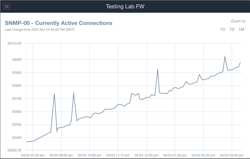
Graph of Currently Active Connections over Time
1. The graph displays currently active connections labeled "SNMP-00" in a testing lab environment, with data recorded on April 24, 2023, starting at 07:53 AM and ending at 03:40 PM (MDT).
2. The vertical axis represents the number of active connections, ranging from 35302.25 to 36124.20.
3. The horizontal axis shows the timeline for the day, marking key times.
4. The line graph shows fluctuations with noticeable spikes in activity at around 09:00 AM and 12:20 PM, followed by a general upward trend.
5. The "Zoom to" section on the top right allows users to adjust the view between 1 day (1D), 7 days (7D), and 1 month (1M) for different data spans.
Cluster Info
A specific SNMP pre-configured template can also be used to monitor the WatchGuard Cluster information about the members configured:
- First Member Role
- First Member System Health
- First Member Hardware Health
- First Member Monitor Port Health
- First Member Weight Average
- Second Member Role
- Second Member System Health
- Second Member Hardware Health
- Second Member Monitor Port Health
- Second Member Weight Average
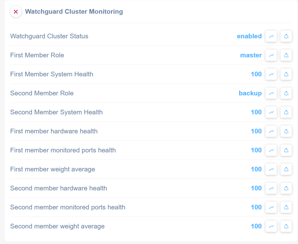
Watchguard Cluster Monitoring Status Overview
1. The cluster status is shown as "enabled."
2. The first member role is labeled as "master."
3. The first member system health displays a value of "100."
4. The second member role is labeled as "backup."
5. The second member system health shows a value of "100."
6. The first member hardware health is "100."
7. The first member monitored ports health is "100."
8. The first member weight average is "100."
9. The second member hardware health is "100."
10. The second member monitored ports health is "100."
11. The second member weight average is "100."
Each value is accompanied by graph and notification icons, indicating options to view data trends or set alerts.
VPN General
A specific SNMP pre-configured template can also be used to monitor the WatchGuard General VPN information:
- Total VPN Entries
- Total Active Inbound Security Associations (SA)
- Total Active Outbound Security Associations (SA)
- Total Inbound IPsec Traffic rate
- Total Outbound IPsec Traffic rate
- Total Inbound IPsec Packets rate
- Total Outbound IPsec Packets rate
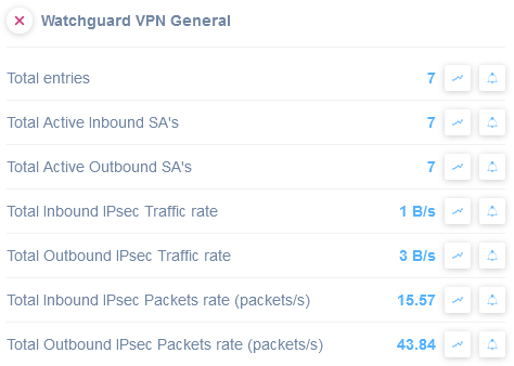
Watchguard VPN General Dashboard Overview
1. The dashboard displays metrics related to VPN connections.
2. "Total entries" shows 7, indicating the number of current VPN entries.
3. "Total Active Inbound SA's" is 7, representing active inbound Security Associations.
4. "Total Active Outbound SA's" is also 7, indicating active outbound Security Associations.
5. "Total Inbound IPsec Traffic rate" is 1 B/s, showing the rate of incoming IPsec traffic.
6. "Total Outbound IPsec Traffic rate" is 3 B/s, indicating the rate of outgoing IPsec traffic.
7. "Total Inbound IPsec Packets rate (packets/s)" notes 15.57, which is the rate of incoming IPsec packets.
8. "Total Outbound IPsec Packets rate (packets/s)" displays 43.84, showing the rate of outgoing IPsec packets.
Use this dashboard to monitor and analyze the traffic and security association metrics of the VPN.
VPN Tunnels
A specific SNMP pre-configured template can also be used to monitor the WatchGuard current active VPN Tunnels:
- Local Ip Address
- Remote Ip Address
- Inbound Traffic rate
- Outbound Traffic rate
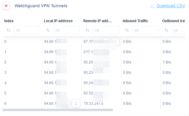
Watchguard VPN Tunnels Interface Overview
1. The interface lists information about VPN tunnels, including columns for Index, Local IP address, Remote IP address, Inbound Traffic, and Outbound Traffic.
2. Each row represents a VPN connection, with specific local and remote IP addresses for each.
3. Inbound and outbound traffic data is displayed in bytes per second (B/s), currently showing 0 B/s for all connections.
4. The interface allows sorting and filtering using the icons above each column.
5. A "Download CSV" option is available in the top right corner for exporting the data.
Sophos Firewall
Four SNMP pre-configured templates are available to monitor specific items for Sophos Firewalls:
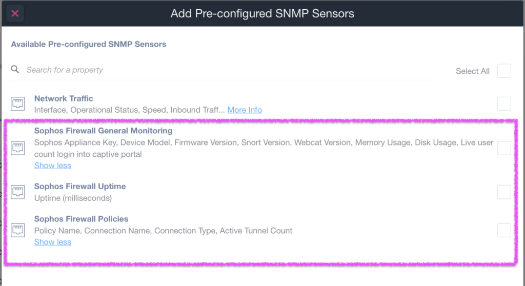
Adding Pre-configured SNMP Sensors in a User Interface.
1. Locate the section titled "Available Pre-configured SNMP Sensors."
2. Use the search bar labeled "Search for a property" to find specific sensors.
3. Sensors are listed with their names and descriptions, including:
- "Network Traffic": Details like interface and speed.
- "Sophos Firewall General Monitoring": Includes appliance key, firmware version, and disk usage.
- "Sophos Firewall Uptime": Shows uptime in milliseconds.
- "Sophos Firewall Policies": Lists policy and connection names.
4. Select checkboxes next to each sensor to choose them. Use "Select All" to choose all available sensors.
General Info
In case of a Sophos Firewall, an SNMP pre-configured template is available to extract the following general properties:
- Sophos Appliance Key
- Device Model
- Firmware Version
- Snort Version
- Webcat Version
- Memory Usage
- Disk Usage
- Live user count (login into captive portal)
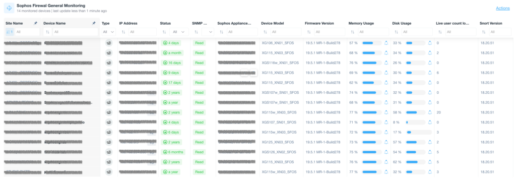
Sophos Firewall General Monitoring Dashboard
1. The dashboard displays a table summarizing 14 monitored devices and their statuses.
2. Columns include Site Name, Device Name, Type, IP Address, Status, SNMP status, Sophos Appliance version, Device Model, Firmware Version, Memory Usage, Disk Usage, Live user count, and Snort Version.
3. Site Name, Device Name, Type, IP Address, and SNMP status are filterable fields.
4. The Status column shows the duration since the last check, indicating device status.
5. Memory Usage and Disk Usage columns display percentage bars for resource monitoring.
6. Live user count and Snort Version columns provide additional device-specific data.
7. Use the “Actions” option on the top right to execute specific tasks for these monitored devices.
Policies
The “Sophos Firewall Policies” is also available.
This template will allow monitoring for each policy configured in the Firewall of the system with the following properties:
- Policy Name
- Connection Name
- Connection Type
- Active Tunnel Count
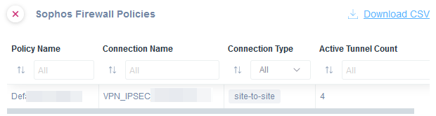
Sophos Firewall Policies Interface
1. The interface lists firewall policies with columns for "Policy Name," "Connection Name," "Connection Type," and "Active Tunnel Count."
2. Each column has a filter option to sort or search through entries, with dropdowns for selecting specific criteria.
3. An example row displays a policy with "Def..." as the policy name, "VPN_IPSEC" as the connection name, "site-to-site" as the connection type, and "4" as the active tunnel count.
4. A "Download CSV" link is available to export the data.
Uptime
The “Sophos Firewall Uptime” is also available.
This template will allow to monitor the uptime of the system, so that the user can monitor if the Sophos Firewall has been restarted for any reason:

Sophos Firewall Uptime Information
1. The heading displays "Sophos Firewall Uptime," which indicates the section provides information about the firewall's operating time.
2. Below the heading, the label "Uptime" is followed by a value showing "69.9 day," indicating the current duration the firewall has been operational without interruption.
3. Two icons are visible next to the uptime value. One of these may represent further details or trends, and the other might relate to alerts or notifications. Hover over these icons or click them for more information.
Licenses Expiration
This template will allow us to monitor the various Sophos Firewall software license expirations:
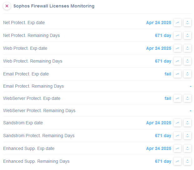
Sophos Firewall Licenses Monitoring Overview
1. **Net Protect.** Expiration date is April 24, 2025, with 671 days remaining.
2. **Web Protect.** Expiration date is April 24, 2025, with 671 days remaining.
3. **Email Protect.** Remaining days show a status of "fail," indicating the license may have expired or is not active.
4. **WebServer Protect.** Remaining days also display "fail," suggesting a similar status issue as Email Protect.
5. **Sandstorm.** Expiration date is April 24, 2025, with 671 days remaining.
6. **Enhanced Support.** Expiration date is April 24, 2025, with 671 days remaining.
For each license type, ensure that expiration dates are monitored, and "fail" statuses are addressed promptly to maintain active protection services.
Fortinet FortiGate
General/Documentation
In the case of a Fortinet FortiGate firewall, a pre-configured SNMP template is available to extract the following general properties:
– Serial Number
– Firmware Version
– Number of Admin users
– CPU usage
– Memory usage
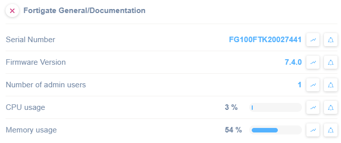
Fortigate General/Documentation Overview
1. The Serial Number is displayed as FG100FTK20027441.
2. The Firmware Version is 7.4.0, indicating the current software version.
3. The Number of Admin Users is listed as 1, showing how many administrative accounts are active.
4. CPU usage is shown at 3%, providing insight into processor load.
5. Memory usage is indicated at 54%, with a progress bar to visualize its consumption.
HW (Hardware) Sensors
A pre-configured SNMP template is available to extract information from FortiGate Firewall hardware sensors.
– Temperature
– BCM Temperature
– CPU Temperature
– External Temperature
– Fan Temperature
– Power Supply unit condition
– Fans speed
In order to monitor each of these, you might set an alert on the Alarm status value:
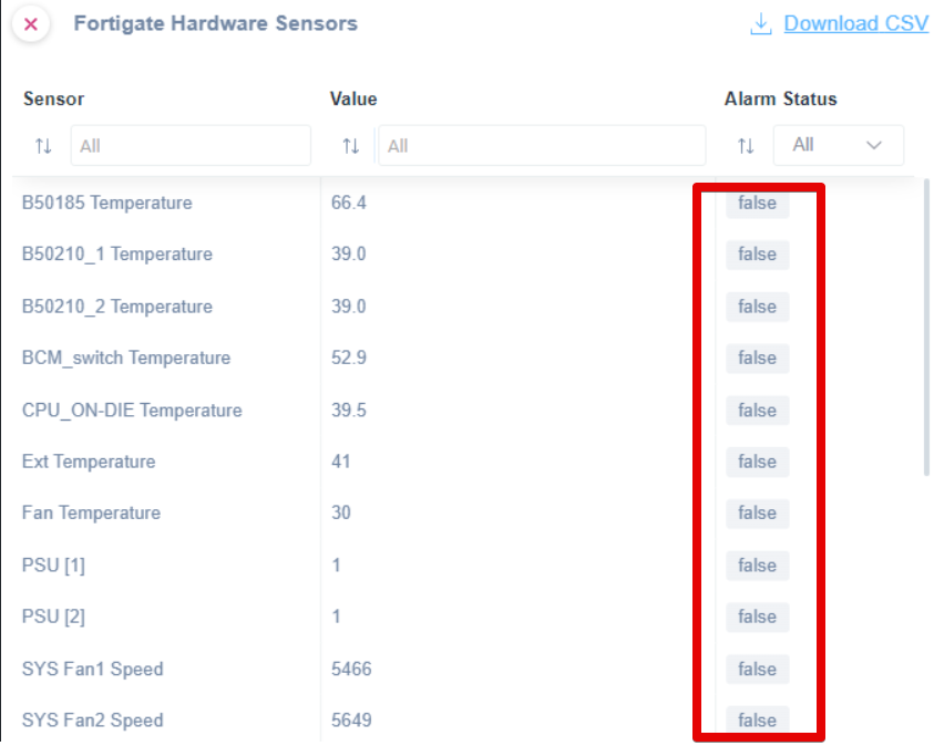
Fortigate Hardware Sensors Interface Overview
1. The interface lists sensors in three columns: Sensor, Value, and Alarm Status.
2. The Sensor column identifies the hardware component, such as "B50185 Temperature" and "SYS Fan1 Speed."
3. The Value column provides the current reading or measurement for each sensor, such as 66.4 for "B50185 Temperature."
4. The Alarm Status column indicates whether there is an alarm condition for each sensor, with all entries currently showing "false," meaning no alarms are active.
5. A "Download CSV" option is available for exporting the data.
FortiGuard Stats
With the ‘FortiGate FortiGuard Stats’ SNMP template, you will be able to monitor the following:
- HTTP/HTTPS requests examined
- HTTP/HTTPS requests allowed
- HTTP/HTTPS requests are blocked
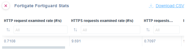
Fortigate Fortiguard Stats Interface
1. The interface displays statistics related to HTTP and HTTPS request examination rates, measured in requests per second (#/s).
2. There are three columns: "HTTP request examined rate", "HTTPS requests examined rate", and a partially visible third column labeled with "HTTP requests…".
3. Each column contains an entry field labeled "All" for filtering data and a numeric value indicating the current examination rate.
4. The HTTP request examined rate shows a value of 0.7108.
5. The HTTPS requests examined rate shows a value of 9.691.
6. An option to download the data as a CSV file is available at the top right.
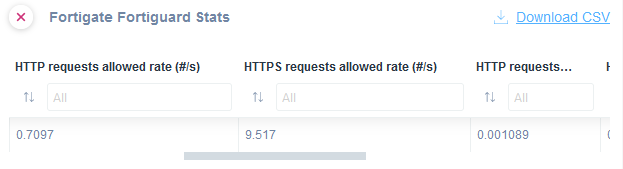
Fortigate Fortiguard Stats Overview
1. View the stats for HTTP requests allowed per second, shown with the value 0.7097.
2. Check the HTTPS requests allowed per second, with a value of 9.517.
3. Observe additional statistics for HTTP requests, highlighted with a value of 0.001089.
4. Use the "Download CSV" link in the top right corner to export this data.
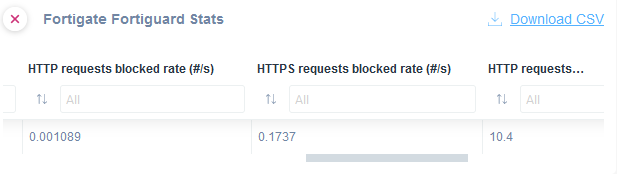
Fortigate Fortiguard Stats Overview
1. The interface shows three columns for monitoring stats: "HTTP requests blocked rate (#/s)," "HTTPS requests blocked rate (#/s)," and an incomplete "HTTP requests..." column title.
2. Each column contains a filter option with a field labeled "All" and an icon for sorting data.
3. Below the filtering fields, values are listed: "0.001089" for HTTP, "0.1737" for HTTPS, and "10.4" for the third column. Use these values to assess the rate of requests blocked per second.
4. A "Download CSV" link in the upper right corner allows you to download the data for further analysis.
WebFilter stats
With the ‘FortiGate WebFilter Stats’ SNMP template you will be able to monitor the following:
- HTTP/HTTPS sessions blocked
- HTTP/HTTPS URL blocked
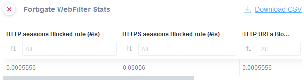
Fortigate WebFilter Stats Overview
1. The interface displays the "Fortigate WebFilter Stats" for web session analysis.
2. It includes three columns with blocked rate statistics:
- "HTTP sessions Blocked rate (#/s)" shows a value of 0.0005556.
- "HTTPS sessions Blocked rate (#/s)" shows a value of 0.06056.
- "HTTP URLs Blocked rate (#/s)" shows a value of 0.0005556.
3. Each column has a search field labeled "All" for filtering results.
4. A "Download CSV" option is available at the top right for exporting data.
VPN Tunnels (Not SSL)
With the ‘FortiGate VPN Tunnels’ SNMP template you will be able to monitor the following:
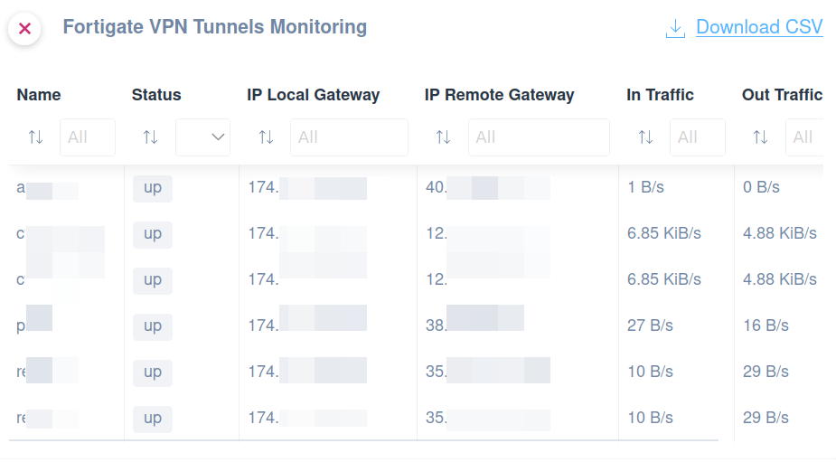
Fortigate VPN Tunnels Monitoring Dashboard.
1. View a table listing VPN tunnels with columns for Name, Status, IP Local Gateway, IP Remote Gateway, In Traffic, and Out Traffic.
2. Each row represents a different VPN tunnel, showing its current status as "up."
3. The IP Local Gateway and IP Remote Gateway columns display specific IP addresses for each tunnel.
4. In Traffic and Out Traffic columns provide the current data transfer rates in B/s or KiB/s.
5. Filters are available at the top of each column to facilitate searching by specific criteria.
6. A "Download CSV" link in the top right corner allows you to export the data.
VPN SSL Tunnels
With the ‘FortiGate SSL VPN Tunnels’ SNMP template you will be able to monitor the following:
- Username
- Source IP
- Connection IP
- Uptime
- Incoming Traffic
- Outgoing Traffic
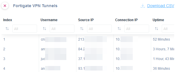
Fortigate VPN Tunnels Overview
1. A table displays information about VPN tunnels, including columns for Index, Username, Source IP, Connection IP, and Uptime.
2. The "Username" column lists partial usernames for connected sessions.
3. The "Source IP" column shows the originating IP address for each connection.
4. The "Connection IP" column contains the destination IP address.
5. The "Uptime" column indicates the duration each VPN tunnel has been active.
6. At the top-right corner, there is an option to download the data as a CSV file.
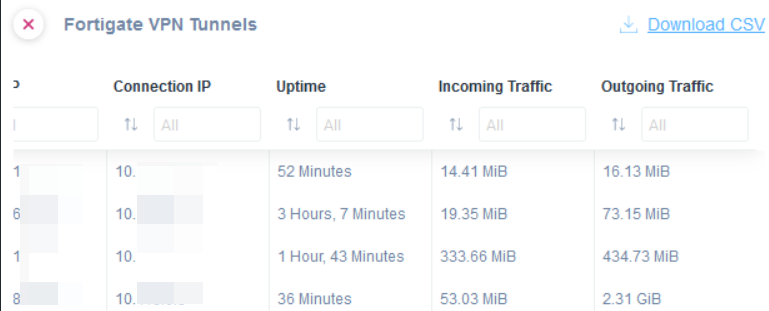
Fortigate VPN Tunnels Table
1. The table lists VPN tunnel details with columns for Connection IP, Uptime, Incoming Traffic, and Outgoing Traffic.
2. Each row corresponds to a VPN tunnel, showing its specific data: Connection IP, how long the tunnel has been active (Uptime), and the amounts of Incoming and Outgoing Traffic in MiB or GiB.
3. Sorting and filtering options are available at the top of each column, allowing you to arrange or limit data based on these categories.
4. A "Download CSV" link at the top right allows you to export the table data in CSV format for further analysis or record-keeping.
IPV4 Sessions
With the ‘FortiGate Session Count (IPV4)’ SNMP template you will be able to monitor the IPV4 session active in the Firewall:
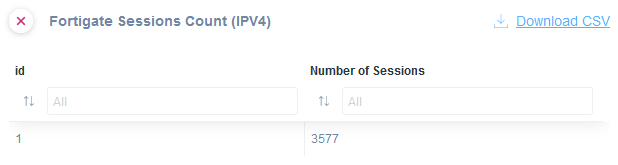
Fortigate Sessions Count Interface
1. The title, "Fortigate Sessions Count (IPv4)," indicates the display of session counts for Fortigate devices using IPv4.
2. The table shows two columns: "id" and "Number of Sessions."
3. Under "id," there is a sort option and a dropdown labeled "All."
4. Under "Number of Sessions," there is a similar sort option and dropdown labeled "All."
5. The data row shows an id value of "1" with "3577" as the number of sessions.
6. A "Download CSV" link is available for exporting the data.
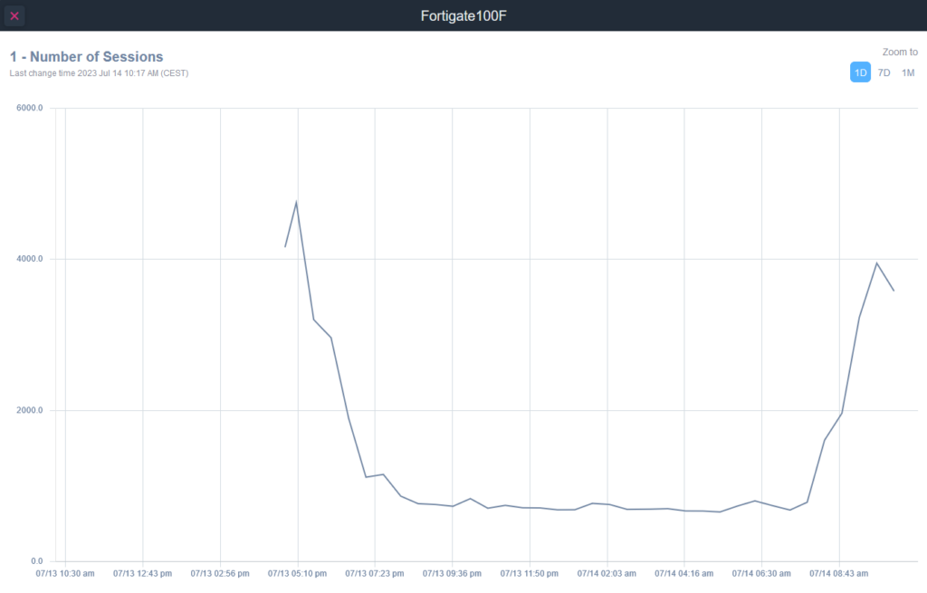
Graph showing the number of sessions over time on Fortigate100F.
1. Title: "Number of Sessions"
2. The graph displays session data from July 13, 10:30 am to July 14, 8:43 am.
3. The vertical axis shows the number of sessions ranging from 0 to 6000.
4. The horizontal axis displays timestamps throughout the monitored period.
5. The session count sharply declines from over 4000 around 12:43 pm to below 1000 at 5:10 pm.
6. A gradual fluctuation occurs overnight, with a notable increase starting around 6:30 am, surpassing 4000 sessions by 8:43 am.
7. The graph can be zoomed to different periods: 1 day, 7 days, or 1 month. Currently, the view is set to 1 day.
IPV6 Session Count
With the ‘FortiGate Session Count (IPV6)’ SNMP template you will be able to monitor the IPV6 session active in the Firewall:
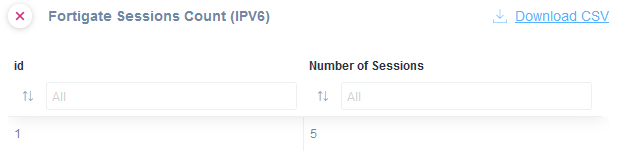
Fortigate Sessions Count (IPv6) Table Overview.
1. The table displays two columns: "id" and "Number of Sessions."
2. Each column provides a filter input box at the top for customized filtering.
3. The "id" column lists session identifiers, while the "Number of Sessions" column shows the session count associated with each ID.
4. A separate option to download the data as a CSV file is available via a link labeled "Download CSV."
HA (High Availability) Properties
In case of a firewall cluster, a Pre-Configure SNMP teamplate is available to extract the following information:
– Mode
– Priority
– Status of a primary override flag
– Automatic Synchronization
– Load-balancing Configuration
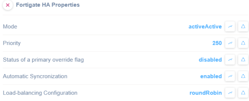
Fortigate HA Properties configuration settings.
1. Set the Mode to "activeActive" for redundancy.
2. Set the Priority to "250" to determine the hierarchy of devices.
3. Ensure the Status of a primary override flag is "disabled" to prevent unnecessary overrides.
4. Enable Automatic Synchronization to keep the system updated.
5. Use "roundRobin" for Load-balancing Configuration to evenly distribute traffic.
HA (High Availability) Stats
With the ‘FortiGate HA Stats’ SNMP template you will be able to monitor the following:
- Serial Number
- CPU Usage
- Memory Usage
- Syncronization Status
- Network Bandwidth Usage
- Session Count rate
- Packets Count rate
- Bytes rate
- IDS/IPS events rate
- Anti-virus events rate

Fortigate HA Stats Overview
1. The table lists monitored devices with columns for device details and performance metrics.
2. Columns include Device Name, IP Address, Serial Number, CPU Usage, Memory Usage, Synchronization Status, Network Bandwidth, Session Count Rate, and Packets Count Rate.
3. Each row represents a device with specific data, such as the IP addresses starting with "192.168" and CPU usage percentages like "4%" and "0%."
4. Memory usage shows percentages, e.g., "75%" and "63%."
5. Synchronization status is labeled as "synchronized" for each device.
6. Network bandwidth is detailed in values such as "6 Mb/s" and "322 Kb/s."
7. Session Count Rate and Packets Count Rate display specific numeric values for each device.
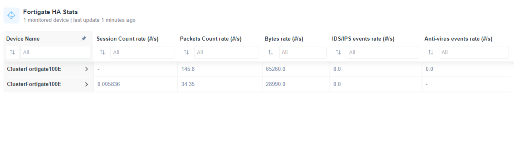
Fortigate HA Stats Display
1. The table displays monitored device statistics, specifically for "ClusterFortigate100E" devices.
2. The columns include various metrics:
- **Session Count rate (#/s)**: Shows current session rates.
- **Packets Count rate (#/s)**: Displays the rate of packet counts, with values like 145.8 and 34.35.
- **Bytes rate (#/s)**: Indicates the data transfer rate in bytes, such as 65260.0 and 28990.0.
- **IDS/IPS events rate (#/s)** and **Anti-virus events rate (#/s)**: Present the rate of intrusion detection/prevention system and anti-virus events, typically at 0.0.
3. Filters and sorting options are available at the top of each column to refine data visibility.
Palo Alto
Palo Alto Firewall General/Documentation
SNMP pre-configured template to extract the following general properties:
- Serial Number
- Chassis Type
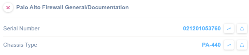
Palo Alto Firewall General Documentation Details
1. Find the serial number associated with the Palo Alto Firewall under "Serial Number." The example shown is 021201053760.
2. Locate the chassis type information below the serial number under "Chassis Type." The example chassis type is PA-440.
Palo Alto Firewall Software Versions
SNMP pre-configured template to extract software/firmware properties:
- Hardware version
- Firmware version
- Application Definition version and release date
- Global Protect Client Package version
- Opswat Database version
- WildFire version and release date
- Antivirus version and release date
- Threat version and release date
- Wildfire Private Cloud Content version
- VPN Client Package version
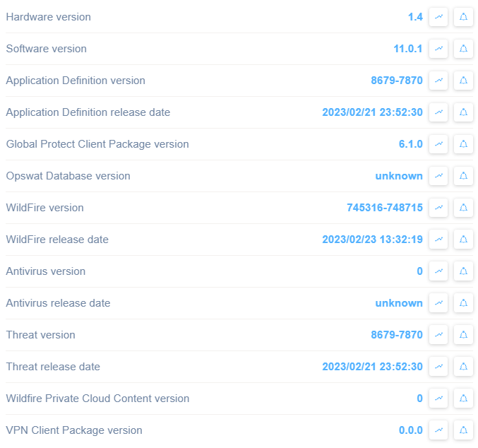
Software Version Information Screen
1. The Hardware version is displayed as 1.4.
2. The Software version is 11.0.1.
3. Application Definition version is listed as 8679-7870.
4. Application Definition release date is 2023/02/21 23:52:30.
5. Global Protect Client Package version is 6.1.0.
6. Opswat Database version is marked as unknown.
7. WildFire version shows 745316-748715.
8. WildFire release date is 2023/02/23 13:32:19.
9. Antivirus version is currently 0.
10. Antivirus release date is unknown.
11. Threat version is displayed as 8679-7870.
12. Threat release date is 2023/02/21 23:52:30.
13. Wildfire Private Cloud Content version shows 0.
14. VPN Client Package version is 0.0.0.
Use this information to verify and manage software components and their update statuses.
Please note that if a value is displayed as 0, the component is not available or not installed.
Palo Alto Firewall Sessions
SNMP pre-configured template to extract active/available sessions:
- Maximum number of sessions
- Active Sessions
- Available Sessions
- TCP Sessions no.
- UDP Sessions no.
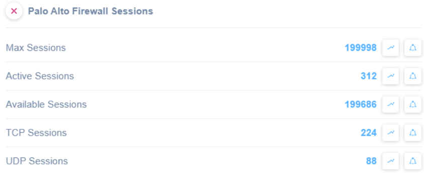
Palo Alto Firewall Session Statistics
1. Max Sessions: Displays the maximum number of sessions allowed, currently set to 199,998.
2. Active Sessions: Shows the number of sessions currently active, which is 312.
3. Available Sessions: Indicates the number of sessions that are still available, at 199,686.
4. TCP Sessions: Lists the number of active TCP sessions, showing 224.
5. UDP Sessions: Displays the number of active UDP sessions, with a count of 88.
Each session type has icons associated with it for additional insights or alerts.
Palo Alto Firewall HA Properties
SNMP pre-configured template to extract HA (High Availability) properties:
- High-Availability State
- Per High-Availability State
- High-Availability Mode
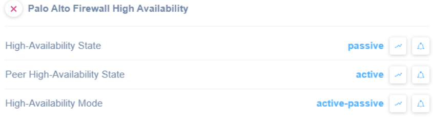
Palo Alto Firewall High Availability Status
1. The "High-Availability State" is labeled as "passive".
2. The "Peer High-Availability State" is labeled as "active".
3. The "High-Availability Mode" is set to "active-passive".
These settings are used to configure and monitor the status and mode of high availability in a Palo Alto Firewall setup, indicating which units are active and passive in a redundant system.
Palo Alto Firewall Zones
SNMP pre-configured template to extract statistics about the connections in each security zone:
- Zone Name
- Active TCP Connections
- Active UDP Connections
- Active IP Connections
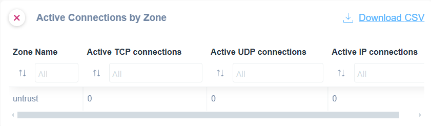
Active Connections by Zone Table Overview
1. The table displays columns for Zone Name, Active TCP connections, Active UDP connections, and Active IP connections.
2. Each column allows sorting and filtering options, indicated by dropdown fields labeled "All."
3. The row beneath shows a zone labeled "untrust" with zero active TCP, UDP, and IP connections.
4. A "Download CSV" link is available for exporting the data.
Palo Alto Firewall Interfaces
SNMP pre-configured template to extract statistics about the connections for each interface:
- Interface description
- Active TCP Connections
- Active UDP Connections
- Active IP Connections
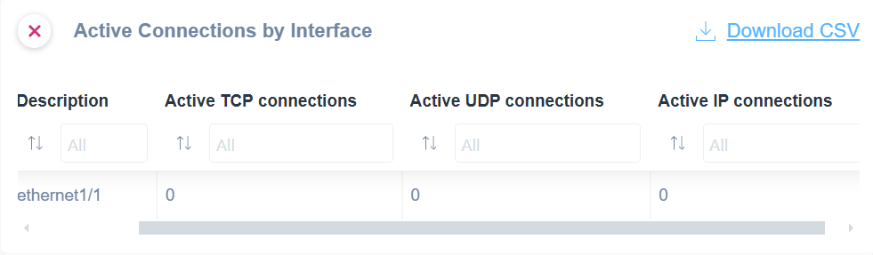
Active Connections by Interface table in a network management tool.
1. The table has columns titled Description, Active TCP connections, Active UDP connections, and Active IP connections.
2. Each column header includes a filter option set to "All."
3. Under the Description column, "ethernet1/1" is listed as the interface name.
4. The interface "ethernet1/1" shows 0 active connections for TCP, UDP, and IP.
5. A "Download CSV" option is available for exporting the data.
SonicWALL
In case of a Sonicwall firewall, an SNMP pre-configured template is available to extract the following general properties:
- Serial Number
- Firmware Version
- CPU Utilization
- Ram Utilization
- Connections Available
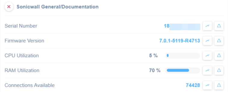
SonicWall Status Overview
1. Check the serial number to identify the device.
2. Verify the firmware version listed as "7.0.1-5119-R4713" to ensure it is up-to-date.
3. Review CPU utilization; currently, it is at 5%, indicating low processing activity.
4. Observe RAM utilization, which is at 70%, suggesting moderate memory usage.
5. Note the number of available connections, totaling 74,428, to understand network capacity.
Audio/Video
Crestron Control System
Crestron System Info
Use this SNMP pre-configured template to monitor Crestron Control System info, like CPU usage and error count:
- CPU Utilization
- CPU Max Utilization
- Error Log Error Count
- Error Log Warning Count
- Error Log Notice Count
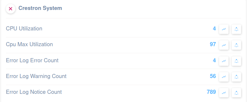
Crestron System Dashboard Overview
1. **CPU Utilization**: Shows a value of 4, indicating current CPU usage level.
2. **CPU Max Utilization**: Displays a value of 97, reflecting the maximum CPU usage recorded.
3. **Error Log Error Count**: Indicates 4 errors logged in the system.
4. **Error Log Warning Count**: Lists 56 warnings found in the error log.
5. **Error Log Notice Count**: The count is 789 for notices in the error log.
Each metric includes options to view trends or set alerts, enabling monitoring and management of system performance and error handling.
Crestron Processor Monitoring
Through this SNMP pre-configured template, you can monitor Crestron Control System Processor info, like system uptime and firmware version:
- Crestron Processor Firmware
- Crestron Processor Power On Time
- Crestron Touchpanel Program
- Crestron Processor Program
- Crestron Processor Current Time
- Crestron Processor Uptime
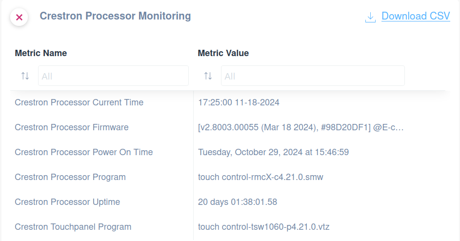
Crestron Processor Monitoring Dashboard
1. The dashboard displays various metrics related to Crestron Processor Monitoring.
2. The "Metric Name" column lists the metrics: Current Time, Firmware, Power On Time, Program, Uptime, and Touchpanel Program.
3. The "Metric Value" column shows corresponding details:
- Current Time: 17:25:00 on November 18, 2024.
- Firmware Version: v2.8003.00055 with additional identifiers.
- Power On Time: October 29, 2024, at 15:46:59.
- Program: touch control-rmcX-c4.21.0.smw.
- Uptime: 20 days 01:38:01.58.
- Touchpanel Program: touch control-tsw1060-p4.21.0.vtz.
4. There is an option to download the data in CSV format via a "Download CSV" link.
Crestron Codec and System Power
Using this SNMP pre-configured template you can monitor Crestron Control System Codec info and System Power, like Codec temperature:
- Codec Call Status
- Codec Connection
- Codec Temperature
- System Power
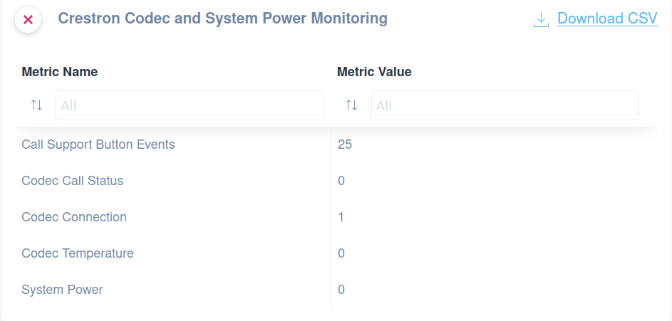
Crestron Codec and System Power Monitoring metrics table.
1. At the top, there are options to filter metrics by their names or values using dropdown menus labeled "Metric Name" and "Metric Value."
2. The table lists various metrics on the left, such as "Call Support Button Events," "Codec Call Status," "Codec Connection," "Codec Temperature," and "System Power."
3. Corresponding metric values are displayed on the right: 25 for Call Support Button Events, 0 for both Codec Call Status and Codec Temperature, 1 for Codec Connection, and 0 for System Power.
4. A "Download CSV" link is available at the top right for exporting the data.