
The Network Topology Map gives you an overview of how devices are connected to each other on the network using a graphical representation.
The feature is accessible from the top menubar by selecting the Topology button:

Network Topology Overview in a Management Interface
1. Access the network topology by selecting the "Topology" tab in the main navigation menu.
2. Observe a central diagram displaying connected network devices. Each device is represented by an icon, labeled with its name and additional details like IP addresses and manufacturer.
3. Notice various link types between devices, indicated by different line styles: direct, manual, outdated, and wireless links, each with a distinct color coding.
4. A small map overlay in the top right corner can be used to get a zoomed-out view of the entire network.
5. Use the search box to filter devices by entering specific text, likely to quickly locate a device within the network layout.
As soon as you deploy the Domotz collector this view will be populated with a ‘basic’ version of the network topology where all the devices are connected to the gateway:
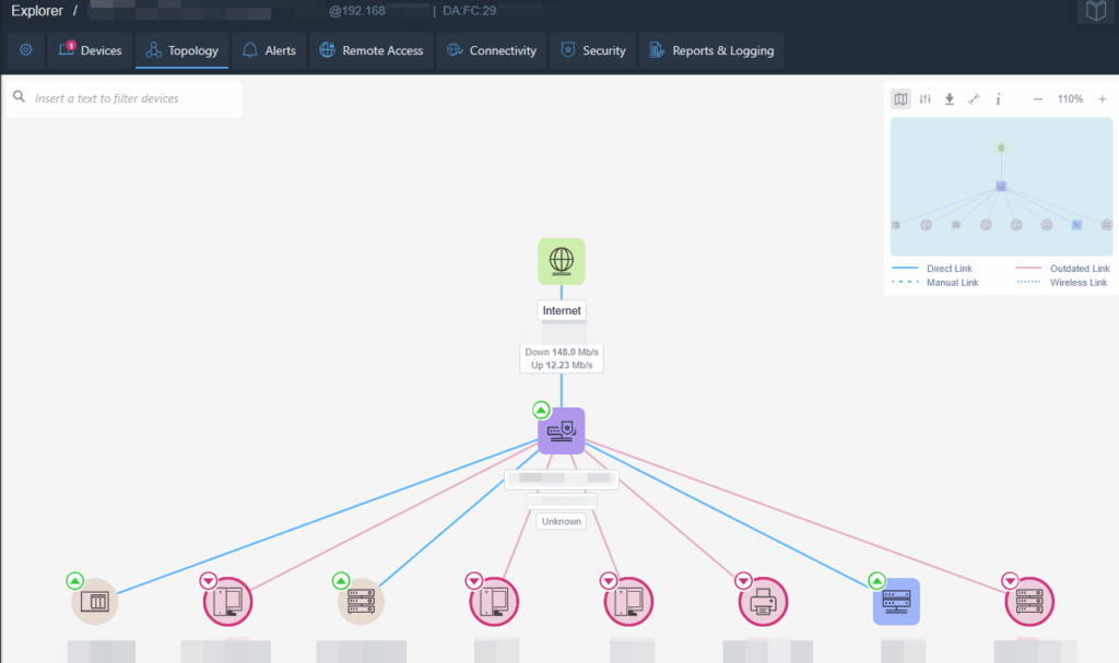
Network Topology Overview
1. The central node, labeled "Internet," shows the current connection speeds: 148.0 Mb/s down and 12.3 Mb/s up.
2. An "Unknown" device connects directly below the Internet node, serving as the main distribution point.
3. Multiple devices branch out from the "Unknown" node, each represented by different icons, indicating various device types.
4. Links between nodes are color-coded: blue for direct links, red for outdated links, and green for wireless links.
5. The navigation bar at the top includes tabs for "Devices," "Topology," "Alerts," "Remote Access," "Connectivity," "Security," and "Reports & Logging," allowing quick access to different functionalities.
6. A search bar is available for filtering devices.
7. A mini-map in the upper-right corner provides an overview of the entire topology layout.
To allow Domotz Pro to improve the Network Topology Map, please make sure to:
- Use Managed Switches compliant to RFC 4188.
- Enable SNMP on the Managed Switches.
- Enable LLDP on the Managed Switches.
- Match the community string configured on the Managed Switches with the ones configured within Domotz Pro.
Once verified the above, on every single Managed Switch, within Domotz Pro, you will be able to see the connected devices in the “Interfaces” tab and the Topology Map will be displayed:
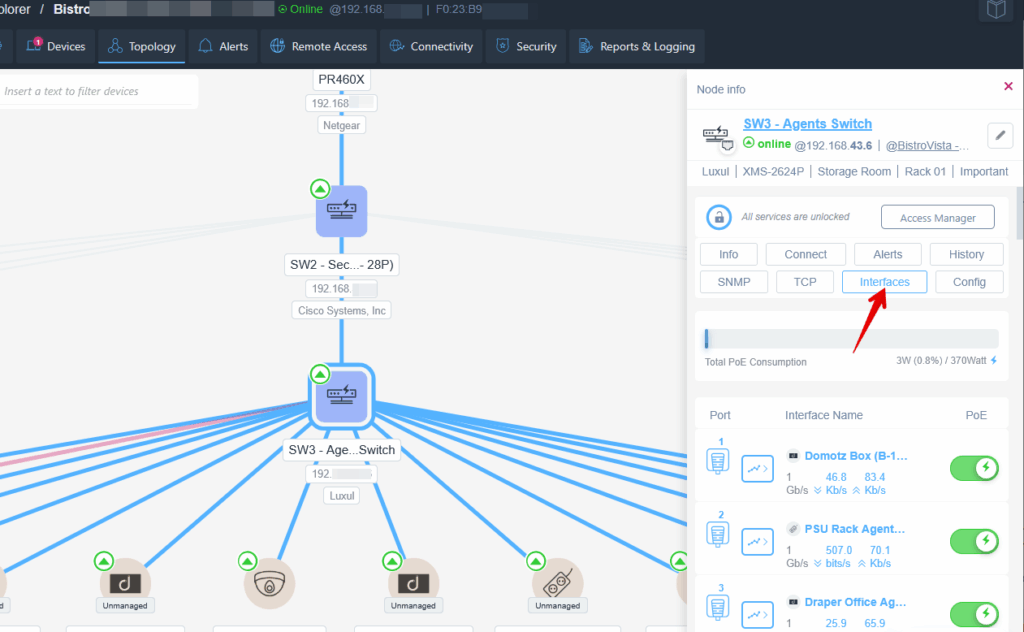
Viewing and Managing Network Interfaces in a Software Dashboard
1. Locate the network diagram showing connected devices, with device names such as "SW2 - Sec... 28P" and "SW3 - Agents Switch."
2. Select "SW3 - Agents Switch" from the diagram. The device information panel on the right displays details including the device status, location, and associated labels.
3. In the information panel, click on the "Interfaces" button to view the list of network interfaces.
4. The panel shows interface details including port numbers, interface names (e.g., "Domotz Box"), and the Power over Ethernet (PoE) status.
5. Review the speed and connectivity status for each interface, displayed in gigabits per second (Gb/s) and kilobits per second (Kb/s).

Network Topology Overview
1. The top of the network hierarchy begins with the Internet, followed by a device labeled "PR6341X."
2. Below "PR6341X" is a node labeled "SW2 - Sec_28PI." Beneath this is another node "SW3 - Agg_Switch1."
3. From "SW3 - Agg_Switch1," multiple connections extend to unmanaged devices, which include several labeled as "Domato," "Lunel," "Mobile Access E," and "Liberty AG."
4. On the right side, connections lead to separate nodes named "PC-B0C-116D1S5," "SB100," and "PDU81001."
5. A legend at the bottom explains the link types: blue for Direct Links, dotted blue for Manual Links, dashed for Outdated Links, and dotted pink for Wireless Links.
6. The top menu bar includes navigation options: Devices, Topology, Alerts, Remote Access, Connectivity, Security, and Reports & Logging.
Symbols and Legend
Internet Node
The Internet Node is the root node of the graph. It reports the global IP address and, if clicked, shows additional network information.
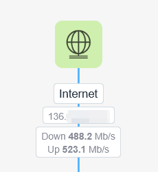
Network Speed Display
1. A globe icon represents the internet connection.
2. The label beneath reads "Internet," indicating the network being monitored.
3. A series of numbers represent the IP address currently in use.
4. "Down 488.2 Mb/s" shows the current download speed.
5. "Up 523.1 Mb/s" indicates the current upload speed.
Network Devices
A violet square icon represents a Switch, a blue one represents a WiFi Access Point, and a green one indicates a Router.
Under each device icon, you can see the device name, IP address, and manufacturer.
When you click on a device, its details panel appears on the right side of the map, allowing you to view information and perform management actions.
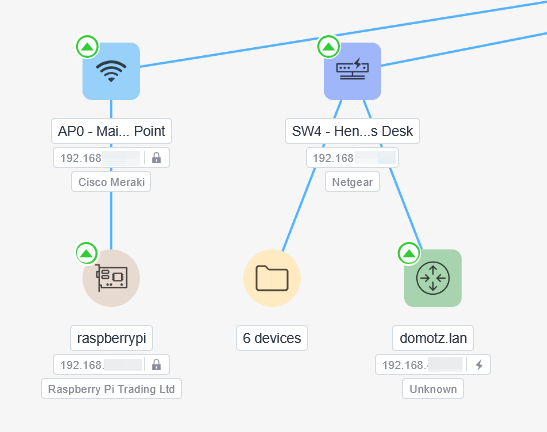
Network Device Overview
1. The "AP0 - Main Point" device is a Cisco Meraki access point with IP address 192.168, linked to a Raspberry Pi device. The Raspberry Pi has IP 192.168 and is associated with Raspberry Pi Trading Ltd.
2. "SW4 - Hen's Desk" is a Netgear switch with IP 192.168, connecting to six additional devices and a device named "domotz.lan." The "domotz.lan" device is unknown but has an IP address starting with 192.168.
Navigating Branches
The “directory-like” icons represent branches of devices that are mapped to a switch or attached to an access point:
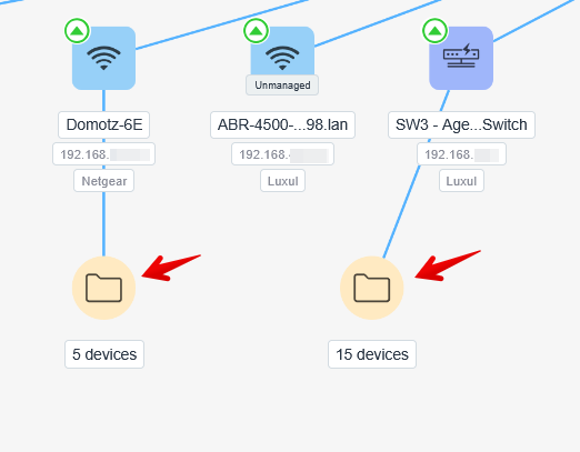
Network Device Overview and Connected Devices
1. Three network devices are displayed: "Domotz-6E," "ABR-4500...98.1an," and "SW3 - Age...Switch."
2. Each device shows its IP address below its name. "Domotz-6E" is associated with Netgear, while the other two are linked with Luxul.
3. The device "Domotz-6E" indicates a connection to five devices, represented by a folder icon below it.
4. The device "SW3 - Age...Switch" indicates a connection to fifteen devices, also represented by a folder icon below it.
5. The folder icons signify the number of devices connected to each network device.
When the “directory-like” icon is clicked, the branch expands to show all attached devices. The branch can then be collapsed by clicking the small icon to the right of the network device.
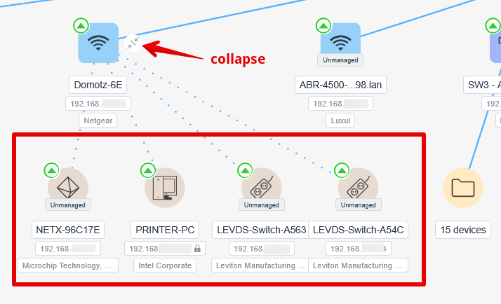
Network Device Hierarchy and Collapse Function
1. At the top left, a wireless device labeled "Domotz-6E" is shown with its IP address and manufacturer, Netgear.
2. Below it, connected devices are listed:
- "NETX-96C17E" with an IP address and manufacturer, Microchip Technology.
- "PRINTER-PC" with an IP address and manufacturer, Intel Corporate.
- Two switches labeled "LEVDS-Switch-A563" and "LEVDS-Switch-A54C," both with IP addresses and manufacturer, Leviton Manufacturing.
3. A "collapse" option is indicated between the main device and its connected devices for organizing or reducing visual data.
4. To the right, another device "ABR-4500...98.lan" is displayed, along with a connected icon for unspecified devices.
Use the collapse function to simplify the view by hiding the detailed list of connected devices under "Domotz-6E."
Round shape
A round shape device is any other IP device on the network, that is, of course, mapped on a netowork device. If the icon is red the device is offline.

Network Device Status and Details
1. The first device, labeled "PC-300-C13025," has an associated IP address and is identified as "CRESTRON ELECTRONICS."
2. The second device, "S100," is marked as "Unmanaged" with an IP address and the status "Unknown." It was last mapped on February 20, 2025.
3. The third device, "PDU81001," also has an IP address and is identified as "CyberPower Systems."
Green circles indicate active status, while a red circle indicates unmanaged status for the "S100" device.
Links

Legend for Link Types in Network Settings.
- A solid blue line indicates a Direct Link.
- A solid pink line represents an Outdated Link.
- A dashed blue line signifies a Manual Link.
- A dashed dotted line denotes a Wireless Link.
- Direct Link: this is a link discovered by the Domotz algorithm. It can’t be modified.
- Manual Link: this link is created when a device is manually mapped on a managed switch port, typically when through that port multiple devices are reached.
- Outdated Link: this link is not valid anymore, because either the device has been removed from the network, or moved to another location where our algorithm can’t discover its connection.
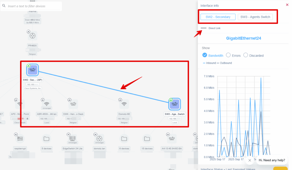
Network Device Connection and Interface Details
1. The left side of the image shows a network topology with two connected devices: "SW2 - Secondary" and "SW3 - Agents Switch."
2. "SW2 - Secondary" is identified as a Cisco device, indicating it's part of a larger network setup.
3. On the right, the interface details panel shows a comparison between the two devices, "SW2 - Secondary" and "SW3 - Agents Switch."
4. The panel highlights a "Direct Link" between the two devices and displays data traffic information with a graph, showing bandwidth usage over time.
5. Blue lines indicate the bandwidth, emphasizing inbound and outbound traffic patterns.
Use this information to understand the network configuration, device connections, and monitor network performance.
Control Panel
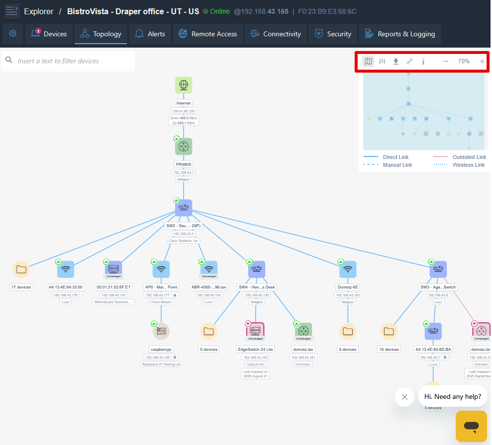
Network Topology Overview in Software Interface
1. The main interface displays the network topology for the BistroVista - Draper office.
2. The top menu includes options: Devices, Topology, Alerts, Remote Access, Connectivity, Security, and Reports & Logging.
3. The central display shows a hierarchical network map starting from the internet, moving through a primary router (PR460X), and branching out to various devices.
4. Devices are identified by icons such as wireless access points, routers, and folders, each labeled with specific IP addresses and additional details like manufacturer names.
5. The top right corner contains a control panel for map view options, zoom functionality, and the current zoom level at 70%.
6. A help chat icon is located in the bottom right for assistance.
The Control Panel at top right contains:
- Network Topology Map Preview:
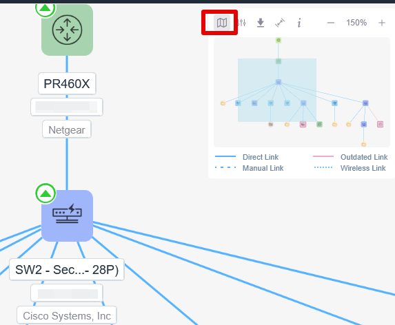
Network Diagram Interface Navigation
1. The network diagram displays various network components connected in a hierarchy. The main devices shown are PR460X and SW2 - Sec...- 28P.
2. PR460X is labeled as part of the Netgear network.
3. SW2 - Sec...- 28P is related to Cisco Systems, Inc.
4. Different link types are indicated by different visual styles: direct links, manual links, outdated links, and wireless links.
5. In the top right, a map icon is highlighted, which suggests toggling the overview map feature to navigate the network structure efficiently.
- Filters Section:
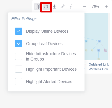
Accessing Filter Settings in a Network Management Tool
1. Locate the filter icon in the toolbar of the network management interface.
2. Click on the filter icon to open the "Filter Settings" menu.
3. In the menu, you can select options such as:
- "Display Offline Devices" to show devices that are not currently online.
- "Group Leaf Devices" to organize devices with no further branches.
- "Hide Infrastructure Devices in Groups" to exclude infrastructure devices from group views.
- "Highlight Important Devices" to emphasize devices marked as important.
- "Highlight Alerted Devices" to identify devices with alerts.
4. Use the checkboxes to enable or disable each filter according to your preference.
- Export Section:
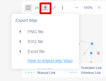
Exporting a Map in the Software Interface.
1. Locate and click the download icon in the toolbar at the top of the map interface.
2. In the dropdown menu labeled "Export Map," choose your preferred file format: PNG, SVG, or Excel by clicking on it.
3. To learn how to import the map into Visio, click on the provided link for detailed instructions.
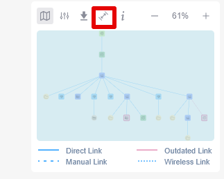
Network map interface with link legend.
1. At the top, there is a toolbar with icons for various actions.
2. The pin icon is highlighted, indicating it is active or selected.
3. Below the toolbar, a network diagram displays nodes and connections.
4. The legend at the bottom identifies link types: blue for Direct Link, green for Manual Link, pink for Outdated Link, and blue dotted for Wireless Link.
- Help on how to improve the topology map:
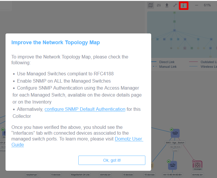
Improving the Network Topology Map Instructions
1. Ensure all Managed Switches are compliant with RFC4188.
2. Enable SNMP on all Managed Switches.
3. Configure SNMP Authentication via the Access Manager for each Managed Switch, either on the device details page or in the Inventory.
4. Alternatively, configure SNMP Default Authentication for the Collector if needed.
After completing these steps, the "Interfaces" tab should display connected devices linked to the managed switch ports. For further details, refer to the Domotz User Guide. To close the instructions, select "Ok, got it!"
How do I refresh the topology map?
The topology map refreshes automatically based on several factors. Depending on your devices, this process could take anywhere from 5 to 30 minutes. In any case, the map will be fully updated within a maximum of 30 minutes.
How do I manually map devices?
In some situations, even though network devices are reachable on a given port, Domotz may not be able to automatically determine which device is physically connected.
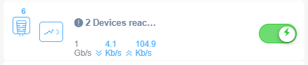
Network Device Status Display
1. The number "6" at the top left indicates the current network channel.
2. Two icons below show network-related functionalities: the first likely represents a server or main network hub, and the second icon resembles a graph, possibly indicating network activity or performance.
3. Text reading "2 Devices" suggests two connected devices are currently detected.
4. Network speed information is displayed, showing 1 Gb/s as the connection speed, with download and upload speeds shown as 4.1 Kb/s and 104.9 Kb/s respectively.
5. A toggle switch on the right is currently turned on, possibly controlling network activity or connection status.
By selecting the port, you can choose the actual device connected to it from the list of reachable devices detected on that port:
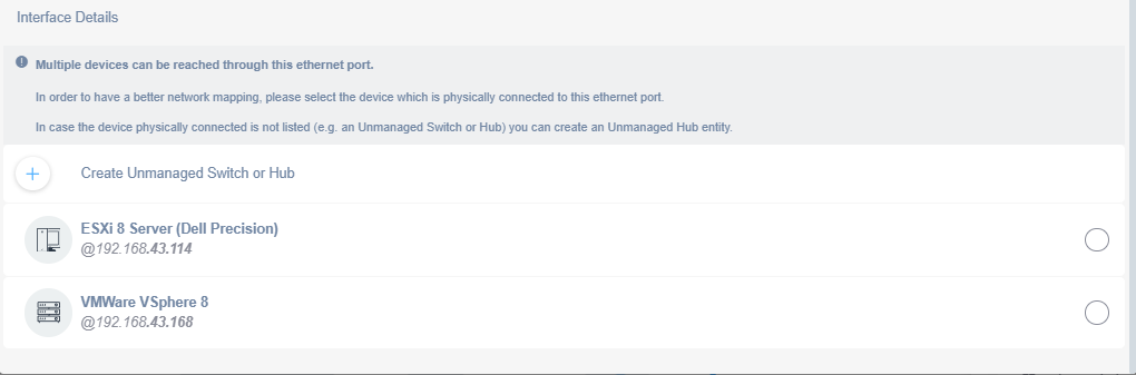
Interface Details for Ethernet Port Configuration
1. Note that multiple devices can connect through this Ethernet port. For accurate network mapping, select the device physically connected to the port.
2. If the connected device is not listed, such as an unmanaged switch or hub, create an unmanaged hub entity.
3. Available devices are displayed for selection:
- "ESXi 8 Server (Dell Precision)" with IP address 192.168.43.114.
- "VMWare VSphere 8" with IP address 192.168.43.168.
4. To add a new device or hub, use the option to "Create Unmanaged Switch or Hub."
If the switch is not correctly reporting reachable devices, you also have the option to manually assign any known device to that port.
To do this, use the Manual Mapping Configuration section and click Add Manual Link:
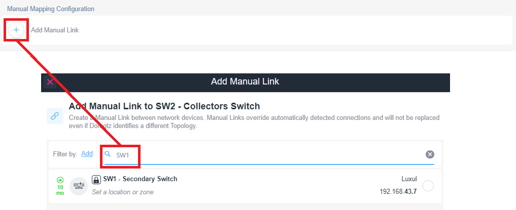
Adding a Manual Link in Network Configuration
1. In the Manual Mapping Configuration section, click on "Add Manual Link."
2. In the "Add Manual Link" dialog box, enter the device identifier (e.g., SW1) in the filter search box.
3. Select the desired device from the search results list to create a manual link.
4. Manual links will override automatically detected connections and maintain their settings unless a different topology is identified.
From there, simply search for the device you want to link and assign it to the port. Manual Links override automatic detection and will persist even if Domotz identifies a different topology later.